
Datasheet


REV. A
AD974
–11–
EXTERNAL CONTINUOUS CLOCK DATA READ AFTER
CONVERSION WITH SYNC OUTPUT GENERATED
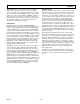
Figure 8 illustrates the method by which data from conversion
“n” can be read after the conversion is complete using a con-
tinuous external clock, with the generation of a SYNC output.
What permits the generation of a SYNC output is a transition of
DATACLK either while CS is high or while both CS and R/C are
low.
With a continuous clock the CS pin cannot be tied low as it
could be with a discontinuous clock. Use of a continuous clock,
while a conversion is occurring, can increase the DNL and
Transition Noise of the AD974.
After a conversion is complete, indicated by BUSY returning
high, the result of that conversion can be read while CS is low
and R/C is high. In Figure 8 clock pulse #0 is used to enable the
generation of a SYNC pulse. The SYNC pulse is actually clocked
out approximately 40 ns after the rising edge of clock pulse #1.
The SYNC pulse will be valid on the falling edge of clock pulse
#1 and the rising edge of clock pulse #2. The MSB will be valid
on the falling edge of clock pulse #2 and the rising edge of clock
pulse #3. The LSB will be valid on the falling edge of clock
pulse #17 and the rising edge of clock pulse #18.
When reading data after the conversion is complete, with the
highest frequency permitted for DATACLK (15.15 MHz) the
maximum possible throughput is approximately 195 kHz and
not the rated 200 kHz.
EXT
DATACLK
CS
R/C
BUSY
SYNC
DATA
0
t
12
t
13
t
14
1 2 3 4 17 18
t
1
t
15
t
10
t
2
t
16
t
17
t
12
t
18
t
18
t
19
BIT 15
(MSB)
BIT 14
BIT 0
(LSB)
Figure 8. Conversion and Read Timing Using an External Continuous Data Clock (EXT/
INT
Set to Logic High)