
Datasheet


AD8628/AD8629/AD8630
Rev. I | Page 15 of 24
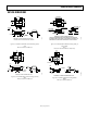
PEAK-TO-PEAK NOISE
Because of the ping-pong action between auto-zeroing and
chopping, the peak-to-peak noise of the AD8628/AD8629/
AD8630 is much lower than the competition. Figure 50 and
Figure 51 show this comparison.
e
n
p-p = 0.5µV
BW = 0.1Hz TO 10Hz
TIME (1s/DIV)
VOLTAGE (0.5µV/DIV)
02735-047
Figure 50. AD8628 Peak-to-Peak Noise
e
n
p-p = 2.3µV
BW = 0.1Hz TO 10Hz
TIME (1s/DIV)
VOLTAGE (0.5µV/DIV)
02735-048
Figure 51. Competitor A Peak-to-Peak Noise
NOISE BEHAVIOR WITH FIRST-ORDER, LOW-PASS
FILTER
The AD8628 was simulated as a low-pass filter (see Figure 53)
and then configured as shown in Figure 52. The behavior of the
AD8628 matches the simulated data. It was verified that noise is
rolled off by first-order filtering. Figure 53 and Figure 54 show
the difference between the simulated and actual transfer functions
of the circuit shown in Figure 52.
470pF
OUT
100kΩ
IN
1kΩ
02735-049
Figure 52. First-Order Low-Pass Filter Test Circuit,
×101 Gain and 3 kHz Corner Frequency
FREQUENCY (kHz)
NOISE (dB)
50
45
40
35
30
25
15
10
5
20
0
0 30 60 10090807050402010
02735-050
Figure 53. Simulation Transfer Function of the Test Circuit in Figure 52
FREQUENCY (kHz)
NOISE (dB)
50
45
40
35
30
25
15
10
5
20
0
0 30 60 10090807050402010
02735-051
Figure 54. Actual Transfer Function of the Test Circuit in Figure 52
The measured noise spectrum of the test circuit charted in
Figure 54 shows that noise between 5 kHz and 45 kHz is
successfully rolled off by the first-order filter.
TOTAL INTEGRATED INPUT-REFERRED NOISE FOR
FIRST-ORDER FILTER
For a first-order filter, the total integrated noise from the
AD8628 is lower than the noise of Competitor A.
3dB FILTER BANDWIDTH (Hz)
RMS NOISE (µV)
10
1
0.1
10 100 10k1k
02735-052
COMPETITOR A
AD8551
AD8628
Figure 55. RMS Noise vs. 3 dB Filter Bandwidth in Hz