
Datasheet


Data Sheet AD8421
Rev. 0 | Page 23 of 28
Overvoltage performance is shown in Figure 14, Figure 15,
Figure 16, and Figure 17. The AD8421 inputs can withstand
a current of 40 mA at room temperature for at least a day. This
time is cumulative over the life of the device. If long periods of
overvoltage are expected, the use of an external protection method
is recommended. Under extreme input conditions, the output
of the amplifier may invert.
RADIO FREQUENCY INTERFERENCE (RFI)
RF rectification is often a problem when amplifiers are used in
applications that have strong RF signals. The problem is intensified
if long leads or PCB traces are required to connect the amplifier
to the signal source. The disturbance can appear as a dc offset
voltage or a train of pulses.
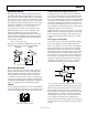
High frequency signals can be filtered with a low-pass filter
network at the input of the instrumentation amplifier, as shown
in Figure 68.
R
R
AD8421
+
V
S
+IN
–IN
0.1µF
10µF
10µF
0.1µF
REF
V
OUT
–V
S
C
D
10nF
C
C
1nF
C
C
1nF
33Ω
33Ω
10123-067
L*
L*
*CHIP FERRITE BEAD.
Figure 68. RFI Suppression
The choice of resistor and capacitor values depends on the
desired trade-off between noise, input impedance at high
frequencies, CMRR, signal bandwidth, and RFI immunity. An
RC network limits both the differential and common-mode
bandwidth, as shown in the following equations:
)2(π2
1
C
D
DIFF
CCR
uencyFilterFreq
+
=
C
CM
RC
uencyFilterFreq
π2
1
=
where C
D
≥ 10 C
C
.
C
D
affects the differential signal, and C
C
affects the common-
mode signal. A mismatch between R × C
C
at the positive input
and R × C
C
at the negative input degrades the CMRR of the
AD8421. By using a value of C
D
that is one order of magnitude
larger than C
C
, the effect of the mismatch is reduced and CMRR
performance is improved near the cutoff frequencies.
To achieve low noise and sufficient RFI filtering, the use of chip
ferrite beads is recommended. Ferrite beads increase their impe-
dance with frequency, thus leaving the signal of interest unaffected
while preventing RF interference to reach the amplifier. They also
help to eliminate the need for large resistor values in the filter,
thus minimizing the system’s input-referred noise. The selection
of the appropriate ferrite bead and capacitor values is a function
of the interference frequency, input lead length, and RF power.
For best results, place the RFI filter network as close as possible
to the amplifier. Layout is critical to ensure that RF signals are
not picked up on the traces after the filter. If RF interference is
too strong to be filtered sufficiently, shielding is recommended.
The resistors used for the RFI filter can be the same as those used
for input protection.
CALCULATING THE NOISE OF THE INPUT STAGE
The total noise of the amplifier front end depends on much more
than the 3.2 nV/√Hz specification of this data sheet. The three
main contributors to noise are: the source resistance, the voltage
noise of the instrumentation amplifier, and the current noise of
the instrumentation amplifier.
In the following calculations, noise is referred to the input (RTI).
In other words, all sources of noise are calculated as if the source
appeared at the amplifier input. To calculate the noise referred
to the amplifier output (RTO), multiply the RTI noise by the
gain of the instru-mentation amplifier.
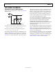
Source Resistance Noise
Any sensor connected to the AD8421 has some output resistance.
There may also be resistance placed in series with inputs for pro-
tection from either overvoltage or radio frequency interference.
This combined resistance is labeled R1 and R2 in Figure 69. Any
resistor, no matter how well made, has an intrinsic level of noise.
This noise is proportional to the square root of the resistor value.
At room temperature, the value is approximately equal to
4 nV/√Hz × √(resistor value in k).
R2
R
G
R1
SENSO
R
AD8421
10123-065
Figure 69. Source Resistance from Sensor and Protection Resistors
For example, assume that the combined sensor and protection
resistance is 4 k on the positive input and 1 k on the negative
input. Then the total noise from the input resistance is
(
)
(
)
=+=×+× 16641444
22
8.9 nV/√Hz