
Datasheet


Data Sheet AD8205
Rev. | Page 11 of 12
APPLICATIONS INFORMATION
A typical application for the AD8205 is high-side measurement
of a current through a solenoid for PWM control of the
solenoid opening. Typical applications include hydraulic
transmission control and diesel injection control.
Two typical circuit configurations are used for this type of
application.
HIGH-SIDE CURRENT SENSE WITH A LOW-SIDE
SWITCH
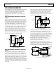
In this case, the PWM control switch is ground referenced. An
inductive load (solenoid) is tied to a power supply. A resistive
shunt is placed between the switch and the load (see Figure 19).
An advantage of placing the shunt on the high side is that the
entire current, including the re-circulation current, can be
measured since the shunt remains in the loop when the switch
is off. In addition, diagnostics can be enhanced because shorts
to ground can be detected with the shunt on the high side.
In this circuit configuration, when the switch is closed, the
common-mode voltage moves down to near the negative rail.
When the switch is opened, the voltage reversal across the
inductive load causes the common-mode voltage to be held one
diode drop above the battery by the clamp diode.
04315-0-018
+IN V
REF
1 +V
S
OUT
–IN GND V
REF
2 NC
INDUCTIVE
LOAD
AD8205
CLAMP
DIODE
42V
BATTER
Y
SHUNT
SWITCH
NC = NO CONNECT
5V
Figure 19. Low-Side Switch
HIGH-SIDE CURRENT SENSE WITH A HIGH-SIDE
SWITCH
This configuration minimizes the possibility of unexpected
solenoid activation and excessive corrosion (see Figure 20). In
this case, both the switch and the shunt are on the high side.
When the switch is off, this removes the battery from the load,
which prevents damage from potential shorts to ground, while
still allowing the recirculating current to be measured and
providing for diagnostics. Removing the power supply from the
load for the majority of the time minimizes the corrosive effects
that could be caused by the differential voltage between the load
and ground.
When using a high-side switch, the battery voltage is connected
to the load when the switch is closed, causing the common-
mode voltage to increase to the battery voltage. In this case,
when the switch is opened, the voltage reversal across the
inductive load causes the common-mode voltage to be held one
diode drop below ground by the clamp diode.
04315-0-019
+IN V
REF
1 +V
S
OUT
–IN GND V
REF
2 NC
INDUCTIVE
LOAD
AD8205
CLAMP
DIODE
42V
BATTER
Y
SHUNT
SWITCH
NC = NO CONNECT
5V
Figure 20. High-Side Switch
Another typical application for the AD8205 is as part of the
control loop in H-bridge motor control. In this case, the
AD8205 is placed in the middle of the H-bridge (see Figure 21)
so that it can accurately measure current in both directions by
using the shunt available at the motor. This is a better solution
than a ground referenced op amp because ground is not
typically a stable reference voltage in this type of application.
This instability in the ground reference causes the
measurements that could be made with a simple ground
referenced op amp to be inaccurate.
The AD8205 measures current in both directions as the
H-bridge switches and the motor changes direction. The output
of the AD8205 is configured in an external reference
bidirectional mode, see the Output Offset Adjustment section.
04315-0-020
+IN V
REF
1 +V
S
OUT
–IN GND V
REF
2 NC
AD8205
SHUNT
5V
2.5V
5V
CONTROLLER
NC = NO CONNECT
MOTOR
Figure 21. Motor Control Application
D