
Datasheet


Data Sheet AD8057/AD8058
Rev. D | Page 13 of 16
APPLICATIONS INFORMATION
DRIVING CAPACITIVE LOADS
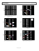
When driving a capacitive load, most op amps exhibit overshoot in
their pulse response. Figure 43 shows the relationship between
the capacitive load that results in 30% overshoot and the closed-
loop gain of an AD8058. It can be seen that, under the gain = +2
condition, the device is stable with capacitive loads of up to 69 pF.
In general, to minimize peaking or to ensure device stability for
larger values of capacitive loads, a small series resistor (R
S
) can
be added between the op amp output and the load capacitor
(C
L
) as shown in Figure 44.
For the setup shown in Figure 44, the relationship between R
S
and C
L
was empirically derived and is shown in Table 4.
CLOSED-LOOP GAIN
500
400
0
51 2 3 4
C
L
(pF)
300
200
100
R
S
= 2.4Ω
R
S
= 0Ω
01064-044
Figure 43. Capacitive Load Drive vs. Closed-Loop Gain
–2.5V
R
G
R
F
R
S
C
L
V
IN
= 200mV p-p
AD8058
0.1µF
10µF
0.1µF
10µF
+2.5V
V
OUT
FET PROBE
01064-045
Figure 44. Capacitive Load Drive Circuit
Table 4. Recommended Value for Resistors R
S
, R
F
, R
G
vs.
Capacitive Load, C
L
, Which Results in 30% Overshoot
Gain R
F
R
G
C
L
(R
S
= 0 Ω) C
L
(R
S
= 2.4 Ω)
1 100 Ω 11 pF 13 pF
2 100 Ω 100 Ω 51 pF 69 pF
3 100 Ω 50 Ω 104 pF 153 pF
4 100 Ω 33.2 Ω 186 pF 270 pF
5 100 Ω 25 Ω 245 pF 500 pF
10 100 Ω 11 Ω 870 pF 1580 pF
50ns/DIV
100mV
–100mV
200mV
–200mV
+OVERSHOOT
29.0%
100mV/DIV
01064-046
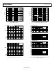
Figure 45. Typical Pulse Response with C
L
= 65 pF, Gain = +2, and V
S
= ±2.5
VIDEO FILTER
Some composite video signals that are derived from a digital
source contain some clock feedthrough that can cause problems
with downstream circuitry. This clock feedthrough is usually at
27 MHz, which is a standard clock frequency for both NTSC
and PAL video systems. A filter that passes the video band and
rejects frequencies at 27 MHz can be used to remove these fre-
quencies from the video signal.
Figure 46 shows a circuit that uses an AD8057 to create a single
5 V supply, 3-pole Sallen-Key filter. This circuit uses a single RC
pole in front of a standard 2-pole active section. To shift the dc
operating point to midsupply, ac coupling is provided by R4, R5,
and C4.
2
3
0.1µF
+
10µF
AD8057
7
4
6
+5V
+5V
R4
10kΩ
R5
10kΩ
C4
0.1µF
R3
49.9Ω
R2
499Ω
C1
100pF
R1
200Ω
R
F
1kΩ
C2
680pF
C3
36pF
01064-047
Figure 46. Low-Pass Filter for Video