
Datasheet


Data Sheet AD7734
Rev. A | Page 13 of 32
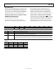
Pin No. Mnemonic Description
9 INTBIAS This pin provides direct access to the analog input’s common node, bypassing the input
resistor divider. In normal circuit configuration, this pin is left open circuit.
10 MUX0 This pin provides direct access to the multiplexer input of Channel 0, bypassing the
input resistor divider. The input voltage range is 0 V to +0.625 V, ±0.625 V, 0 V to +1.25 V,
or ±1.25 V referenced to the INTBIAS pin. In normal circuit configuration, this pin is left
open circuit.
11, 14, 15, 18 BIAS0–BIAS3 These inputs are used to level shift the analog inputs. These signals are used to ensure
that the differential signal seen by the internal buffer amplifier is within its common-
mode range. The BIAS0 to BIAS3 pins will normally be connected to 2.5 V.
12, 13, 16, 17 AIN0–AIN3 Analog Inputs.
19 BIASLO BIASLO, in association with BIASHI, is used to set the analog input common-mode
voltage. Assuming the BIAS0 to BIAS3 and BIASHI pins are connected to 2.5 V, the analog
input voltages are referenced to the voltage at BIASLO. In normal circuit configuration,
this pin should be connected to 0 V.
20 BIASHI BIASHI, in association with BIASLO, is used to set the analog input common-mode
voltage. In normal circuit configuration, this pin should be connected to 2.5 V.
21 REFIN(+) Positive Terminal of the Differential Reference Input. REFIN(+) voltage potential can lie
anywhere between AV
DD
and AGND. In normal circuit configuration, this pin should be
connected to a 2.5 V reference voltage.
22 REFIN(–) Negative Terminal of the Differential Reference Input. REFIN(–) voltage potential can lie
anywhere between AV
DD
and AGND. In normal circuit configuration, this pin should be
connected to a 0 V reference voltage.
23 AGND Ground Reference Point for Analog Circuitry.
24
RDY
Logic Output. Used as a status output in both conversion mode and calibration mode. In
conversion mode, a falling edge on this output indicates that either any channel or all
channels have unread data available, according to the RDYFN bit in the I/O port register.
In calibration mode, a falling edge on this output indicates that calibration is complete
(see the Digital Interface Description section for more details).
25 DOUT Serial data output with serial data being read from the output shift register on the part.
This output shift register can contain information from any AD7734 register, depending
on the address bits of the communications register.
26 DIN Serial data input (Schmitt triggered) with serial data being written to the input shift
register on the part. Data from this input shift register is transferred to any AD7734
register, depending on the address bits of the communications register
27 DV
DD
Digital Supply Voltage, 3 V or 5 V Nominal.
28 DGND Ground Reference Point for Digital Circuitry.