
Datasheet


AD7195
Rev. 0 | Page 30 of 44
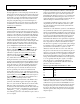
Continuous Conversion Mode
Continuous conversion is the default power-up mode. The
AD7195 converts continuously, and the
RDY
bit in the status
register goes low each time a conversion is complete. If
CS
is
low, the DOUT/
RDY
line also goes low when a conversion
is completed. To read a conversion, the user writes to the
communications register, indicating that the next operation is
a read of the data register. When the data-word has been read
from the data register, DOUT/
RDY
goes high. The user can
read this register additional times, if required. However, the
user must ensure that the data register is not being accessed at
the completion of the next conversion or else the new conversion
word is lost.
When several channels are enabled, the ADC continuously
loops through the enabled channels, performing one conversion
on each channel per loop. The data register is updated as soon
as each conversion is available. The DOUT/
RDY
pin pulses low
each time a conversion is available. The user can then read the
conversion while the ADC converts on the next enabled channel.
If the DAT_STA bit in the mode register is set to 1, the contents
of the status register are output along with the conversion each
time that the data read is performed. The status register
indicates the channel to which the conversion corresponds.
DIN
SCLK
DOUT/RDY
CS
0x58 0x58
DATA DATA
0
8771-030
Figure 22. Continuous Conversion