
Datasheet


AD7151
Rev. 0 | Page 19 of 28
CONFIGURATION REGISTER
Address Pointer 0x0F
8 Bits, Read/Write, Factory Preset 0x19
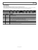
Table 12. Configuration Register Bit Map
Bit Bit 7 Bit 6 Bit 5 Bit 4 Bit 3 Bit 2 Bit 1 Bit 0
Mnemonic ThrFixed ThrMD1 ThrMD0 EnConv – MD2 MD1 MD0
Default 0 0 0 1 0 0 0 1
Table 13.Configuration Register Bit Descriptions
Bit Mnemonic Description
7 ThrFixed
ThrFixed = 1 sets the fixed threshold mode. The output reflects comparison of data and a fixed (constant) value
of the threshold register.
ThrFixed = 0 sets the adaptive threshold mode. The output reflects comparison of data to the adaptive
threshold. The adaptive threshold is set dynamically, based on the history of the previous data.
These bits set the output comparator mode.
Output Active When
ThrMD1 ThrMD0 Threshold Mode Adaptive Threshold Mode Fixed Threshold Mode
0 0 Negative data < average – sensitivity Data < Threshold
0 1 Positive data > average + sensitivity Data > Threshold
1 0 In-Window data > average – sensitivity
AND
data < average + sensitivity
-
6
5
ThrMD1
ThrMD0
1 1 Out-Window data < average – sensitivity
OR
data > average + sensitivity
-
4 EnConv Enables conversion. This bit must be 1 for proper operation.
3 – This bit must be 0 for proper operation.
Converter mode of operation setup.
MD2 MD1 MD0 Mode Description
0 0 0 Idle Part is fully powered up but performing no conversion.
0 0 1
Continuous
Conversion
Part is repeatedly performing conversions, provided the
EnConv bit is set.
0 1 0 Single Conversion
Part performs a single conversion, provided the EnConv bit
is set. After finishing the conversion(s), the part goes to the
idle mode.
0 1 1 Power-Down
Powers down the on-chip circuits, except the digital
interface.
2
1
0
MD2
MD1
MD0
1 X X Reserved Do not use these modes.