
Datasheet


AD712
Rev. H | Page 17 of 20
FILTERS
ACTIVE FILTER APPLICATIONS
In active filter applications using op amps, the dc accuracy of
the amplifier is critical to optimal filter performance. The
amplifier offset voltage and bias current contribute to output
error. Offset voltage is passed by the filter and can be amplified
to produce excessive output offset. For low frequency applications
requiring large value input resistors, bias currents flowing
through these resistors also generate an offset voltage.
In addition, at higher frequencies, the op amp dynamics must
be carefully considered. Here, slew rate, bandwidth, and open-
loop gain play a major role in op amp selection. The slew rate
must be fast as well as symmetrical to minimize distortion. The
amplifier bandwidth in conjunction with the filter gain dictates
the frequency response of the filter.
The use of a high performance amplifier such as the AD712
minimizes both dc and ac errors in all active filter applications.
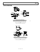
SECOND-ORDER LOW-PASS FILTER
Figure 48 depicts the AD712 configured as a second-order,
Butterworth low-pass filter. With the values as shown, the
corner frequency is 20 kHz; however, the wide bandwidth of the
AD712 permits a corner frequency as high as several hundred
kilohertz. Equations for component selection are as follows:
R1 = R2 = A user selected value (10 kΩ to 100 kΩ, typical)
C1 (in farads) =
()
()
()
12
414.1
Rf
cutoff
π
()
()
()
12
707.0
2
Rf
C
cutoff
π
=
+15V
1/2
AD712
0.1µF
0.1µF
–15V
V
OUT
V
IN
C1
560pF
R2
20kΩ
R1
20kΩ
C2
280pF
+
–
0
0823-048
Figure 48. Second-Order Low-Pass Filter
An important property of filters is their out-of-band rejection.
The simple 20 kHz low-pass filter shown in Figure 48, can be
used to condition a signal contaminated with clock pulses or
sampling glitches that have considerable energy content at high
frequencies.
The low output impedance and high bandwidth of the AD712
minimize high frequency feedthrough as shown in Figure 49.
The upper trace is that of another low cost BiFET op amp
showing 17 dB more feedthrough at 5 MHz.
REF 20.0 dB
m
10dB/DIV RANGE 15.0dBm
OFFSET .0 Hz
0dB
CENTER 5 000 000.0Hz
RBW 30kHz
SPAN 10 000 000.0Hz
ST .8 SEC
VBW 30kHz
TYPICAL BIFET
AD712
00823-049
Figure 49. High Frequency Feedthrough