
Datasheet


AD5421 Data Sheet
Rev. G | Page 24 of 36
POWER-ON DEFAULT
The AD5421 powers on with all registers loaded with their default
values and with the loop current in the alarm state set to 3.2 mA
or 22.8 mA/24 mA (depending on the state of the ALARM_
CURRENT_DIRECTION pin and the selected range). The
AD5421 remains in this state until it is programmed with new
values. The SPI watchdog timer is enabled by default with a
timeout period of 1 sec. If there is no communication with the
AD5421 within 1 sec of power-on, the FAULT pin is set.
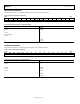
Table 11.
Range
ALARM_CURRENT_
DIRECTION
Power-On Loop
Current (mA)
4 mA to 20 mA 0 3.2
4 mA to 20 mA 1 22.8
3.8 mA to 21 mA 0 3.2
3.8 mA to 21 mA 1 22.8
3.2 mA to 24 mA 0 3.2
3.2 mA to 24 mA 1 24
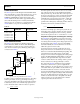
HART COMMUNICATIONS
The AD5421 can be interfaced to a Highway Addressable
Remote Transducer (HART) modem to enable HART digital
communications over the 2-wire loop connection. Figure 47
shows how the modem frequency shift keying (FSK) output is
connected to the AD5421.
09128-054
R
L
200kΩ
LOOP–
DRIVE
COMC
IN
REG
IN
V
LOOP
AD5421
HART_OUT
HART_IN
HART
MODEM
C
HART
C
SLEW
Figure 47. Connecting a HART Modem to the AD5421
To achieve a 1 mA p-p FSK current signal on the loop, the voltage
at the C
IN
pin must be 111 mV p-p. Assuming a 500 mV p-p
output from the HART modem, this means that the signal must
be attenuated by a factor of 4.5. The following equation can be
used to calculate the values of the C
HART
and C
SLEW
capacitors.
HART
SLEW
HART
C
C
C +
=
5.4
From this equation, the ratio of C
HART
to C
SLEW
is 1 to 3.5. This
ratio of the capacitor values sets the amplitude of the HART
FSK signal on the loop. The absolute values of the capacitors set
the response time of the loop current, as well as the bandwidth
presented to the HART signal connected at the C
IN
pin. The
bandwidth must pass frequencies from 500 Hz to 10 kHz. The
two capacitors and the internal impedance, R
DAC
, form a high-
pass filter. The 3 dB frequency of this high-pass filter should be
less than 500 Hz and can be calculated as follows:
( )
SLEW
HART
DAC
dB
CCR
f
+××π×
=
2
1
3
To achieve a 500 Hz high-pass 3 dB frequency cutoff, the com-
bined values of C
HART
and C
SLEW
should be 21 nF. To ensure the
correct HART signal amplitude on the current loop, the final
values for the capacitors are C
HART
= 4.7 nF and C
SLEW
= 16.3 nF.
Output Noise During Silence and Analog Rate of Change
The AD5421 has a direct influence on two important specifi-
cations relating to the HART communications protocol: output
noise during silence and analog rate of change. Figure 25 shows
the measurement of the AD5421 output noise in the HART
extended bandwidth; the noise measurement is 0.2 mV rms,
within the required 2.2 mV rms value.
To meet the analog rate of change specification, the rate of
change of the 4 mA to 20 mA current must be slow enough so
that it does not interfere with the HART digital signaling. This
is determined by forcing a full-scale loop current change
through a 500 Ω load resistor and applying the resulting voltage
signal to the HART digital filter (HCF_TOOL-31). The peak
amplitude of the signal at the filter output must be less than
150 mV. To achieve this, the rate of change of the loop current
must be restricted to less than approximately 1.3 mA/ms.
The output of the AD5421 naturally slews at approximately
880 mA/ms, a rate that is far too great to comply with the
HART specifications. To reduce the slew rate, a capacitor can be
connected from the C
IN
pin to COM, as described in the Loop
Current Slew Rate Control section. To reduce the slew rate
enough so that the HART specification is met, a capacitor value
in the region of 4.7 µF is required, resulting in a full-scale transition
time of 500 ms. Many applications regard this time as too slow,
in which case the slew rate needs to be digitally controlled by
writing a sequence of codes to the DAC register so that the
output response follows the desired curve.