
Specifications


Connections and Wiring
32
NetLinx Integrated Controllers
AXlink Port and LED
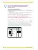
All NI units have an AXlink port and adjacent status LED (FIG. 20). This port allows the NI to
support AMX Legacy AXlink devices such as G3 touch panels (ex: CP4/A) and PosiTrack Pilot
devices. A green LED shows AXlink data activity. When the AXlink port is operating normally,
blink patterns include:
Off - No power, or the controller is not functioning properly
1 blink per second - Normal operation.
3 blinks per second - AXlink bus error. Check all AXlink bus connections.
The AXlink port can be used to supply power to downstream AXlink-compatible devices as long as
both the power required is LESS THAN 2 Amps total and the external power supply feeding the NI
unit has the necessary power capability.
Wiring Guidelines
The Integrated Controllers use a 12 VDC-compliant power supply to provide power through the
rear 2-pin 3.5 mm mini-Phoenix PWR connector. Use the power requirements referenced in the
product’s Specifications table to determine the power draw.
The incoming PWR and GND cable from the power supply must be connected to the corresponding
locations within the PWR connector.
Wiring length guidelines
Refer to the following tables for the wiring length information used with the different types of
NetLinx Integrated Controllers:
FIG. 20 AXlink connector and LED
GND
AXM
AXP
PWR
AXLink
NI AXlink connector
This unit should only have one source of incoming power.
Using more than one source of power to the Controller can result in damage to the
internal components and a possible burn out.
Apply power to the unit only after installation is complete.
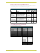
Wiring Guidelines - NI-3000 & NI-4000@ 900 mA
Wire size Maximum wiring length
18 AWG 120.41 feet (39.70 meters)
20 AWG 76.45 feet (23.30 meters)
22 AWG 49.36 feet (15.04meters)
24 AWG 30.08 feet (9.17 meters)