
User guide


Linear Feedback Shift Register (LFSR), the next pattern can be determined from the previous pattern.
When the PRBS checker receives a portion of the received pattern, it can generate the next sequence of
bits to verify the next data sequence received is correct.
The PRBS generator and checker in Arria 10 devices are hardened blocks shared between the Standard
and Enhanced datapaths through the PCS. Therefore, they have only one set of control signals and
registers. The data lines from the various PCSs and shared PRBS generator are MUXed before they are
sent to the PMA. When the PRBS generator is enabled, the data on the PRBS data lines is selected to be
sent to the PMA. Either the data from the PCS or the data generated from the PRBS generator can be sent
to the PMA at any time.
The PRBS generator and checker can be configured for two widths of the PCS-PMA interface: 10 bits and
64 bits. PRBS9 is available in both 10-bit and 64-bit PCS-PMA widths. All other PRBS patterns are
available in 64-bit PCS-PMA width only. The PRBS generator and checker patterns can only be used
when the PCS-PMA interface width is configured to 10 bits or 64 bits. For any other PCS-PMA width, to
ensure the correct clocks are provided to the PRBS blocks you must first reconfigure the width to either 10
or 64 bits before using the PRBS generator and checker. For example, when the transceiver is configured
to a 20-bit PCS/PMA interface, you must first reconfigure the PCS-PMA width to 10 bits before setting up
the PRBS generator and checker. The PRBS setup will not automatically change the PCS/PMA width.
The 10-bit PCS-PMA width for PRBS9 is available for lower frequency testing. You can configure PRBS9
in either 10-bit or 64-bit width, based on the data rate. The FPGA fabric-PCS interface must run in the
recommended speed range of the FPGA core. Therefore, you must configure PRBS9 in one of the two bit
width modes, so that the FPGA fabric-PCS interface parallel clock runs in this operating range.
Examples:
• If you want to use PRBS9 and the data rate is 2.5 Gbps, you can use the PRBS9 in 10-bit mode (PCS-
PMA width = 10). In this case, the parallel clock frequency = Data rate / PCS-PMA width = 2500
Mbps/10 = 250 MHz.
• If you want to use PRBS9 and the data rate is 6.4 Gbps, you can use the PRBS9 in 64-bit mode (PCS-
PMA width = 64). In this case, the parallel clock frequency = Data rate / PCS-PMA width = 6400
Mbps/64 = 100 MHz.
• If you want to use PRBS9 and the data rate is 12.5 Gbps, you can use the PRBS9 in 64 bit mode (PCS-
PMA width = 64). In this case, the parallel clock frequency = Data rate / PCS-PMA width = 12500
Mbps/64 = 195.3125 MHz.
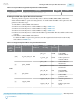
Table 6-31: PRBS Supported Polynomials and Data Widths
Use the 10-bit mode of PRBS9 when the data rate is lower than 3 Gbps.
Pattern Polynomial 64-Bit 10-Bit
PRBS7 G(x) = 1+ x
6
+ x
7
X
PRBS9 G(x) = 1+ x
5
+ x
9
X X
PRBS15 G(x) = 1+ x
14
+ x
15
X
PRBS23 G(x) = 1+ x
18
+ x
23
X
PRBS31 G(x) = 1+ x
28
+ x
31
X
To generate a pattern of 1s and 0s, use the Arria 10 square wave generator and specify a length of consecu‐
tive 1s and 0s. The square wave generator in Arria 10 devices is a hardened block shared between the
Standard and Enhanced datapaths similar to the PRBS generator and checker. The square wave generator
only supports the 64-bit PCS-PMA width. There are no control and status signals available when using
the square wave generator.
6-48
Using PRBS and Square Wave Data Pattern Generator and Checker
UG-01143
2015.05.11
Altera Corporation
Reconfiguration Interface and Dynamic Reconfiguration
Send Feedback