
User guide


• Rate Match FIFO Basic (Double Width) Mode on page 2-300
For more information about implementing rate match FIFO in basic double width mode.
• How to Implement GbE, GbE with IEEE 1588v2 in Arria 10 Transceivers on page 2-104
For more information about implementing rate match FIFO in GigE mode.
• PCI Express (PIPE) on page 2-228
For more information about implementing rate match FIFO in PCIe mode.
• How to Implement PCI Express (PIPE) in Arria 10 Transceivers on page 2-245
For more information about implementing rate match FIFO in PIPE mode.
• Using the Basic/Custom, Basic/Custom with Rate Match Configurations of Standard PCS on page
2-290
8B/10B Decoder
The general functionality for the 8B/10B decoder is to take a 10-bit encoded value as input and produce
an 8-bit data value and a 1-bit control value as output. In configurations with the rate match FIFO
enabled, the 8B/10B decoder receives data from the rate match FIFO. In configurations with the rate
match FIFO disabled, the 8B/10B decoder receives data from the word aligner. The 8B/10B decoder
operates in two conditions:
• When the PCS-PMA interface width is 10 bits and FGPA fabric-PCS interface width is 8 bits
• When the PCS-PMA interface width is 20 bits and FPGA fabric-PCS interface width is 16 bits
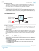
Figure 5-42: 8B/10B Decoder in Single-Width and Double-Width Mode
Single-Width Mode
Current Running Disparity
datain[19:10]
rx_dataout[15:8]
rx_datak[1]
rx_errdetect[1]
rx_disperr[1]
recovered clock or
tx_clkout[0]
datain[9:0]
rx_dataout[7:0]
rx_datak[0]
rx_errdetect[0]
rx_disperr[0]
recovered clock or
tx_clkout[0]
Double-Width Mode
8B/10B Decoder
(MSB Byte)
8B/10B Decoder
(LSB Byte)
datain[9:0]
rx_dataout[7:0]
rx_datak
rx_errdetect
rx_disperr
recovered clock or
tx_clkout[0]
8B/10B Decoder
(LSB Byte)
When the PCS-PMA interface width is 10 bits, only one 8B/10B decoder is used to perform the
conversion. When the PCS-PMA interface width is 20 bits, two cascaded 8B/10B decoders are used. The
10-bit LSByte of the received 20-bit encoded data is decoded first and the ending running disparity is
forwarded to the 8B/10B decoder responsible for decoding the 10-bit MSByte. The cascaded 8B/10B
decoder decodes the 20- bit encoded data into 16-bit data + 2-bit control identifier. The MSB and LSB of
the 2-bit control identifier correspond to the MSByte and LSByte of the 16-bit decoded data code group.
The decoded data is fed to the byte deserializer or the RX FIFO.
5-50
8B/10B Decoder
UG-01143
2015.05.11
Altera Corporation
Arria 10 Transceiver PHY Architecture
Send Feedback