
Manual


13 • AlphaLinQ™ Visual Nurse Call System
Wire Connections
Use crimp-style connectors for all wire connections. Do not use wire nuts.
AlphaLinQ Master Station™:
No internal wiring is necessary for the AlphaLinQ™ Master Station unless you have multiple ELM116 modules and
the common connections need to be jumped.
VPS101, VPS102, VSS110 Call Stations:
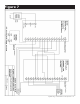
Connect wires as shown in Figures 8-9.
EPS155/EPS337/EPS339 Emergency Stations:
Connect wires as shown in Figures 8-9.
VDS150 Duty Stations:
Connect wires as shown in Figures 8-9.
CDL101LED Corridor Lights, CDL102LED Corridor Zone Lights:
Connect wires as shown in Figures 8-9.
AC152 Power & Control Unit:
Connect wires as shown in Figures 8-9. Also connect secondary from the SS106 Transformer (24 VAC, 30 VA con-
nections) to the AC152 as shown in Figures 8-9. Do not connect transformer primary to power source until
entire installation is completed and checked for shorts and grounds.
Connections Checkout
Recheck all connections to equipment. If all wires and connections are satisfactory, connect primary coil of SS106
Transformer to source of 120 VAC 60 cycles (40 watts max.) and operation of system can be checked according to
System Test Instructions next in this section.
System Test Instructions
Before proceeding with a system test, all stations should be set to normal conditions as follows:
AlphaLinQ™ 100 Series Master Station
No initialization is necessary.
VPS101, VPS102 Call Stations:
If the call cord push button has been pressed, reset the station by pressing the CANCEL button.
VSS110 Call Stations:
If the call button has been pressed, reset the station by pressing the CANCEL button.
EPS339 Emergency Stations:
If the call/cancel switch is pressed to the IN position, twist the switch to the OUT position to reset the station.
EPS155/EPS337 Emergency Stations and EPS156 Code Station:
If the call cord has been pulled or the switch has been pulled down, reset the station by pushing the switch up.
VDS150 Duty Stations:
Slide the TONE OFF switch up.