
User Manual


Table Of Contents
- Alienware Aurora R9 Service Manual
- Working inside your computer
- Removing and installing components
- Inside view of your computer
- System-board components
- Recommended tools
- Screw list
- Left-side cover
- Top cover
- Right-side cover
- 2.5-inch hard drive
- 3.5-inch hard drive
- 2.5-inch hard-drive cage
- 3.5-inch hard-drive cage
- 460 W power-supply unit
- 850 W Power-supply unit
- Right tron-light board
- Processor liquid-cooling assembly
- Coin-cell battery
- Memory modules
- Solid-state drive
- Single-graphics card
- Dual-graphics card
- Front bezel
- Top bezel
- Bottom cover
- Processor fan and heat-sink assembly
- Processor
- Wireless card
- Antennas
- Front I/O-panel
- Front-chassis fan
- Top-chassis fan
- Power-button board
- System board
- Device drivers
- System setup
- Troubleshooting
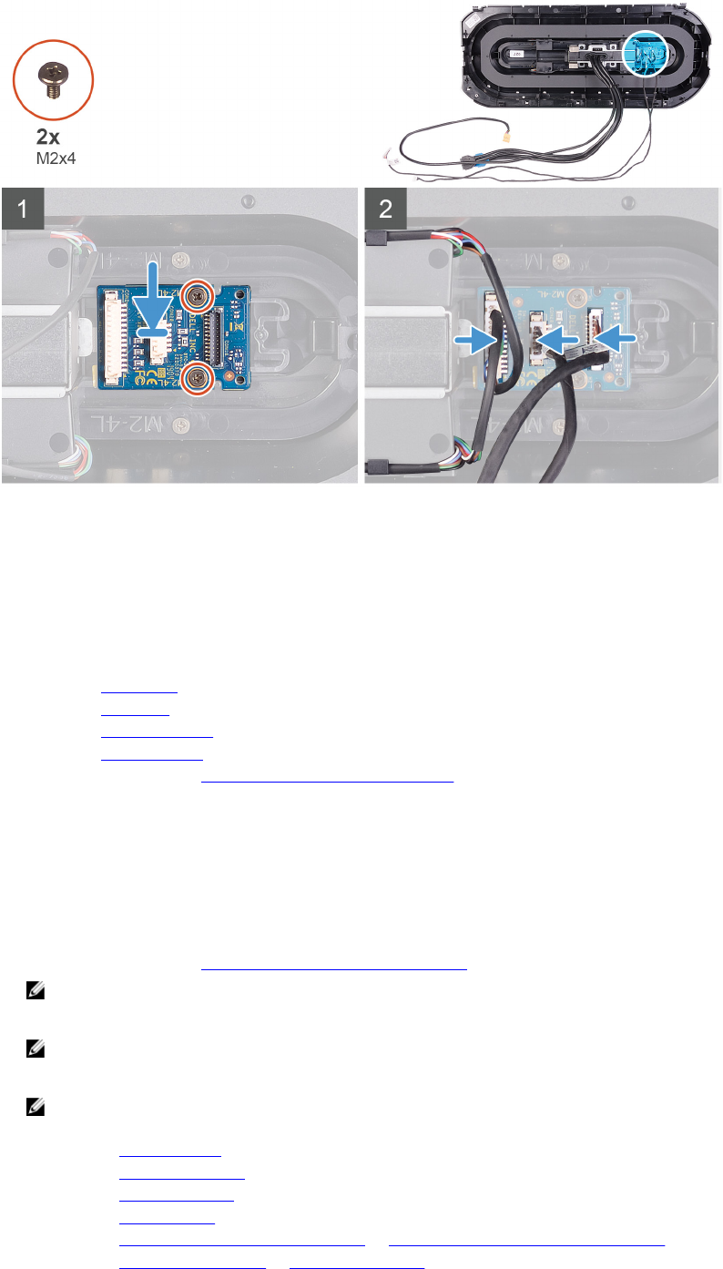
Steps
1. Align the screw holes on the power-button module with the screw holes on the front bezel.
2. Replace the two screws (M2x4) that secure the power-button module to the front bezel.
3. Connect the cables to the power-button module.
Next steps
1. Install the front bezel.
2. Install the top-cover.
3. Install the right-side cover.
4. Install the left-side cover.
5. Follow the procedure in After working inside your computer.
System board
Removing the system board
Prerequisites
1. Follow the procedure in Before working inside your computer.
NOTE: Your computer’s Service Tag is stored in the system board. You must enter the Service Tag in the BIOS
setup program after you replace the system board.
NOTE: Replacing the system board removes any changes you have made to the BIOS using the BIOS setup
program. You must make the appropriate changes again after you replace the system board.
NOTE: Before disconnecting the cables from the system board, note the location of the connectors so that you
can reconnect the cables correctly after you replace the system board.
2. Remove the left-side cover.
3. Remove the memory modules.
4. Remove the solid-state drive.
5. Remove the wireless card.
6. Remove the processor liquid-cooling assembly or processor fan and heat-sink assembly, as applicable.
7. Remove the single-graphics card or dual-graphics card, as applicable.
86