
User's Manual

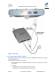
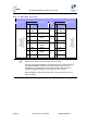


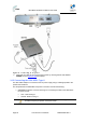

Table Of Contents
- 1.1 Purpose
- 1.4 Referenced Documentation
- 2.1 MicroMAX Frequency Ranges
- 2.2 System Components
- 2.3 Customer Benefits
- 2.4 Architecture
- 2.5 Power
- 2.6 Models
- 3.1 Package Contents
- 3.2 Required Tools
- 3.3 Radio Site Planning
- 4.1 MicroMAX BSR
- 4.2 SDA-4S Type II
- 4.3 SDA-4SDC Type II
- 5.1 Physical Dimensions
- 5.2 Ports
- 6.1 Physical Dimensions
- 6.2 Ports
- 6.3 LEDs
- 6.4 Mounting the GPSD
- 6.5 GPSD Architecture
- 7.1 Physical Dimensions
- 7.2 Ports
- 7.3 Crimping GPS Cable
- 7.4 Contact Socket Crimping
- 8.2 Redundant PS Unit
- 9.1 Pole-Mounting the BSR
- 9.2 Wall-Mounting the BSR (Optional)
- 9.3 Installing the SDA-4S
- 10.1 Desktop mounting
- 10.2 Rack mounting
- 12.1 Rack Mounting
- 12.2 Connecting Redundant PS Unit
- 13.1 Connecting the BSR to the SDA-4S
- 13.2 SDA-4S Type II
- 13.3 Connecting the BSR to BSDU
- 13.4 Connecting BSDU to Network
- 13.5 Connecting BSDUs
- 13.6 Connecting BSDU for SNMP Management
- 14.1 Connecting the SDA-4S Type II
- 14.2 Connecting the SDA-4SDC Type II
- 14.3 Connecting SDA-4S to Ethernet Network
- 15.1 Housing the Connectors
- 15.2 Connecting to the SDA-4SDC
- 16.1 Connections
- 16.2 Power Cable Assembly
- 16.3 Housing the Connectors
- 16.4 Cable Connection
- 17.1 Lightning Protection
- 17.2 Cable Preparation (for grounding)
- 17.3 FM Interference & ESD Protection Recommendations
- 17.4 Connecting Lightning and Surge Protector
- 17.5 Lightning and Surge Protection Connection Scenarios
- 18.1 Connecting GPS Antenna to BSDU
- 19.1 Environmental
- 19.2 Glossary of Terms
- 19.3 Revision History
- 19.4 Contact Information

MicroMAX Hardware Installation User Guide
Page 63 Commercial in Confidence UWB-D00068 Rev J
¾ Connector pinouts:
Table 23 - BSR- BSDU connections
Straight-through CAT-5 PVC 4 Pair 24 AWG cables
BSR BSDU 15-pin D-type
male
Pin Function
Wire color Wire
pair
PinFunction
15-pin D-type
male
1 +48
VDC
Blue / White 1 +48
VDC
2 48 RTN Blue
1
2 48 RTN
3 Tx+ Orange /
White
3 Rx+
4 Tx- Orange
2
4 Rx-
5 Rx+ Green /
White
5 Tx+
6 Rx- Green
3
6 Tx-
7 Sync.+ Brown /
White
7 Sync.+
8 Sync.- Brown
4
8 Sync.-
Note: A CAT-5e cable connects to the 15-pin D-type port; therefore, only
eight pins are used (i.e. pins 9 through 15 are not used).
The wire color-coding described in the table (and shown in the figure below)
is AIRSPAN WIMAX's standard for wire color-coding. However, if you
implement your company's wire color-coding scheme, ensure wires are
paired and twisted according to pin functions (e.g. Rx+ with Rx-).
When the BSR is connected to an SDA, pins 7 and 8 are not used (i.e. no
synchronization).