
User's Manual

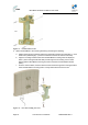


Table Of Contents
- 1.1 Purpose
- 1.4 Referenced Documentation
- 2.1 MicroMAX Frequency Ranges
- 2.2 System Components
- 2.3 Customer Benefits
- 2.4 Architecture
- 2.5 Power
- 2.6 Models
- 3.1 Package Contents
- 3.2 Required Tools
- 3.3 Radio Site Planning
- 4.1 MicroMAX BSR
- 4.2 SDA-4S Type II
- 4.3 SDA-4SDC Type II
- 5.1 Physical Dimensions
- 5.2 Ports
- 6.1 Physical Dimensions
- 6.2 Ports
- 6.3 LEDs
- 6.4 Mounting the GPSD
- 6.5 GPSD Architecture
- 7.1 Physical Dimensions
- 7.2 Ports
- 7.3 Crimping GPS Cable
- 7.4 Contact Socket Crimping
- 8.2 Redundant PS Unit
- 9.1 Pole-Mounting the BSR
- 9.2 Wall-Mounting the BSR (Optional)
- 9.3 Installing the SDA-4S
- 10.1 Desktop mounting
- 10.2 Rack mounting
- 12.1 Rack Mounting
- 12.2 Connecting Redundant PS Unit
- 13.1 Connecting the BSR to the SDA-4S
- 13.2 SDA-4S Type II
- 13.3 Connecting the BSR to BSDU
- 13.4 Connecting BSDU to Network
- 13.5 Connecting BSDUs
- 13.6 Connecting BSDU for SNMP Management
- 14.1 Connecting the SDA-4S Type II
- 14.2 Connecting the SDA-4SDC Type II
- 14.3 Connecting SDA-4S to Ethernet Network
- 15.1 Housing the Connectors
- 15.2 Connecting to the SDA-4SDC
- 16.1 Connections
- 16.2 Power Cable Assembly
- 16.3 Housing the Connectors
- 16.4 Cable Connection
- 17.1 Lightning Protection
- 17.2 Cable Preparation (for grounding)
- 17.3 FM Interference & ESD Protection Recommendations
- 17.4 Connecting Lightning and Surge Protector
- 17.5 Lightning and Surge Protection Connection Scenarios
- 18.1 Connecting GPS Antenna to BSDU
- 19.1 Environmental
- 19.2 Glossary of Terms
- 19.3 Revision History
- 19.4 Contact Information

MicroMAX Hardware Installation User Guide
Page 57 Commercial in Confidence UWB-D00068 Rev J
11 Mounting the GPS
Depending on individual customer requirements and environmental influences, there are several
available options for mounting the GPS:
¾ Pole Mounting: Using the 1" – 14 threads, the GPS can be mounted onto a standard
antenna mast or mounting adapter. (not supplied)
¾ Mounting Plate: Using three 10-32 UNF screws, the GPS can be mounted on a flat
surface with three holes on a 1.75-inch diameter circle. (not supplied)
¾ Direct Mounting: The unit may be mounted directly to a suitable structure that has been
provided with holes suited to the GPS mounting details.
Figure 40 - GPS pole mounting
Note: When mounting the GPS on a metal pole that is in physical contact
with the ground, the GPS will not synchronize. To enable synchronization,
you need to isolate the GPS from the pole using isolation material.
Note: The GPS should not be mounted near to FM transmitters, whether
broadcast radio, or 2-way radio, as this can cause a loss of sync. Mount the
GPS away from the transmitting antenna, or physically shield from the
transmitting antenna, this will assist with proper GPS operation.