EX355P Programmable Bench Power Supply
Table of Contents Introduction 2 Specification 3 Safety 5 Installation 6 Connections 6 Operation 7 Remote Operation 8 Remote Commands 9 Maintenance 12 Instructions en Francais 13 Bedienungsanleitung auf Deutsch 21 Istruzioni in Italiano 29 Instrucciones en Español 37 1
Introduction The EX355P is a digitally controlled version of the EX355 with an isolated RS-232 interface. Using mixed-mode regulation technology it provides 0 to 35V at 0 to 5A in a compact and lightweight unit. The EX355P offers a low-cost solution for a basic programmable PSU, and will be sufficient for many applications where the sophistication and complexity of GPIB is not needed.
Specification General specifications apply for the temperature range 5°C to 40°C. Accuracy specifications apply for the temperature range 18°C to 28°C after 1 hour warm-up with no load and calibration at 23°C. Typical specifications are determined by design and are not guaranteed. OUTPUT Voltage Range: 0V to 35V minimum Current Range: 0.01A to 5A minimum Voltage Setting: By coarse and fine rotary encoders or RS-232 interface. Resolution 10mV. Setting accuracy 0.3% ± 20mV (for V >0.
RS-232 CONTROL Interface: RS-232 interface, fully opto-isolated from power supply output. 9-pin D connector. Baud Rate: Variable from 600 baud to 9,600 baud. Remote Functions: Set voltage, Set Current, Set Output On/Off, Read Voltage, Read Current, Read On/Off, Read Mode (CV or CC). Setting Accuracy: Voltage 0.3% ± 20mV (for V >0.1V). Current 0.6% ± 20mA (for I >0.1A). Setting Resolution: Voltage 10mV. Current 10mA. Readback Accuracy: Voltage 0.3% ± 100mV. Current 0.6% ± 20mA.
Safety This power supply is a Safety Class I instrument according to IEC classification and has been designed to meet the requirements of EN61010-1 (Safety Requirements for Electrical Equipment for Measurement, Control and Laboratory Use). It is an Installation Category II instrument intended for operation from a normal single phase supply. This instrument has been tested in accordance with EN61010-1 and has been supplied in a safe condition.
Installation Mains Operating Voltage Check that the instrument operating voltage marked on the rear panel is suitable for the local supply. Mains Lead When a three core mains lead with bare ends is provided this should be connected as follows: BROWN - MAINS LIVE BLUE - MAINS NEUTRAL GREEN/YELLOW - EARTH Safety Earth Symbol When fitting a fused plug a 5 amp fuse should be fitted inside the plug.
Operation Setting Up the Output With the POWER switch on (l) and the output off the output voltage and current limit can be accurately preset using the VOLTAGE and CURRENT controls; the left-hand meter shows the set voltage and the right-hand meter shows the set maximum current. output switch is switched on, the ON lamp lights; the left-hand meter still shows the When the preset voltage but the right-hand meter now shows the actual load current.
Note that the output terminals are rated at 15A maximum; if several outputs are operated in parallel to source higher currents than this the junction should be made at a separate point, not one of the terminals. Ventilation The power supply is very efficient but nevertheless can generate significant heat at full power. The supply relies on convection cooling only and it is therefore important that ventilation is never restricted if performance and safety are to be maintained.
Baud rate is set as described above; the other interface parameters are fixed as follows: Start Bits: 1 Parity: None Data Bits: 8 Stop Bits: 1 RS232 Character Set Any ASCII code can be used. Bit 7 of ASCII codes is ignored, i.e. assumed to be low. No distinction is made between upper and lower case characters in command mnemonics and they may be freely mixed. The ASCII control codes between 00H and 31H are ignored, except for 0AH (Line Feed, LF) which is used as a command terminator.
Command List This section lists all commands and queries implemented in this instrument. The commands are listed in alphabetical order within the function groups. The following nomenclature is used: , CR followed by LF. A number with no fractional part, i.e. an integer. A number in a fixed point format, e.g. 11.52, 3.61, etc. Set-up Commands V Set the voltage to . The value of must be in Volts; no multipliers are allowed.
ERR? Returns the value in the error register in the form ERR 0 = no errors. 1 = command not recognised. 2 = command value outside instrument limits. Miscellaneous Commands *RST Resets the instrument to the default power-up settings (1.00V, 1.00A, output off). *IDN? Returns the instrument identification.
Maintenance The Manufacturers or their agents overseas will provide repair for any unit developing a fault. Where owner wish to undertake their own maintenance work, this should only be done by skilled personnel in conjunction with the service manual which may be purchased directly from the Manufacturers or their agents overseas. Fuse The correct fuse type is: 10 Amp 250V HBC time-lag(T), 5 x 20mm.
Sécurité Cet instrument est de Classe de sécurité 1 suivant la classification IEC et il a été construit pour satisfaire aux impératifs EN61010-1 (impératifs de sécurité pour le matériel électrique en vue de mesure, commande et utilisation en laboratoire). Il s'agit d'un instrument d'installation Catégorie II devant être exploité depuis une alimentation monophasée habituelle. Cet instrument a été soumis à des essais conformément à EN61010-1 et il a été fourni en tout état de sécurité.
Installation Tension d’utilisation secteur Vérifier que la tension opérationnelle de l'instrument indiquée sur le panneau arrière est appropriée pour l'alimentation locale. Câble secteur Relier de la manière suivante tout câble secteur à trois conducteurs à fils nus: MARRON - SECTEUR SOUS TENSION BLEU - SECTEUR NEUTRE VERT/JAUNE - TERRE Symbole Terre de protection Lors du montage d'une fiche à fusible, mettre un fusible de 5 A à l'intérieur de la fiche.
Fonctionnement Réglage de la sortie L’interrupteur POWER (alimentation) sur (l) et la sortie éteinte, il est possible de régler avec précision la limite de tension et de courant de sortie au moyen des commandes VOLTAGE (Tension) et CURRENT (Courant); l’appareil de mesure gauche indique la tension réglée et l’appareil droit le courant maximum réglé.
Il faut noter que le bloc peut uniquement recevoir du courant, mais non le consommer, de sorte qu’il n’est pas possible de mettre en opposition de phase les blocs reliés en série. Il est possible de relier le bloc en parallèle avec d’autres, afin de produire des courants de haute intensité.
Connecteur RS232 Le connecteur d'interface série 9 voies type D est situé sur le panneau arrière de l'instrument.
Commandes à distance Formats des commandes à distances RS232 Le tampon d'entrée de l'instrument accepte une seule commande (ou interrogation) à la fois, sous interruption, d'une manière transparente pour les autres opérations de l'instrument. Les commandes et interrogations doivent être envoyées comme spécifié dans la liste des commandes et doivent se terminer par le code de fin de commande 0AH (saut de ligne, LF). Noter que les paramètres sont séparés de l’entête de commande par un espace (20H).
Commandes de collationnement V? Renvoie la tension de sortie réglée en Volts sous le format numérique . La syntaxe de la réponse est V Exemple : I? Renvoie la limite d’intensité de sortie réglée en A sous le format numérique . La syntaxe de la réponse est I Exemple : VO? Si la limite d’intensité de sortie réglée est de 1,00 A, la réponse à la commande I? sera I 1.00. Lit et renvoie la tension réelle de sortie en Volts sous le format numérique .
Maintenance Le Constructeur ou ses agents à l'étranger répareront tout bloc qui tombe en panne. Si le propriétaire de l'appareil décide d'effectuer lui-même la maintenance, ceci doit uniquement être effectué par un personnel spécialisé qui doit se référer au manuel d’entretien que l'on peut se procurer directement auprès du Constructeur ou de ses agents à l'étranger. Fusible Type de fusible correct: 10 A 250 V HBC temporisé (T), 5 x 20 mm.
Sicherheit Dieses Gerät wurde nach der Sicherheitsklasse (Schutzart) I der IEC-Klassifikation und gemäß den europäischen Vorschriften EN61010-1 (Sicherheitsvorschriften für elektrische Meß-, Steuer, Regel- und Laboranlagen) entwickelt. Es handelt sich um ein Gerät der Installationskategorie II, das für den Betrieb von einer normalen einphasigen Versorgung vorgesehen ist. Das Gerät wurde gemäß den Vorschriften EN61010-1 geprüft und wurde in sicherem Zustand geliefert.
Installation Netzbetriebsspannung Sicherstellen, daß die auf der Geräterückwand angegebene Betriebsspannung mit der Versorgungsspannung am Ort übereinstimmt. Netzkabel Steht nur ein Netzkabel ohne Stecker zur Verfügung, so ist es wie folgt anzuschließen: BRAUN - STROMFÜHRENDER LEITER BLAU - NULLEITER GRÜN/GELB - SCHUTZLEITER Schutzleitersymbol Bei Steckern mit eingebauten Sicherungen sollte eine 5 Ampere-Sicherung verwendet werden.
Betrieb Einstellung des Ausgangs Bei eingeschaltetem POWER-Schalter (Netz I) und ausgeschaltetem Ausgang läßt sich die Ausgangsspannung und Strombegrenzung mit Hilfe der Knöpfe VOLTAGE (Spannung) und CURRENT (Strom) genau voreinstellen. Die linke Anzeige zeigt die eingestellte Spannung und die rechte den eingestellten Maximalstrom an. Bei eingeschaltetem Ausgang leuchtet die ON Lampe auf.
Ausgangsspannung der Ausgangsspannung des Geräts, bei dem der Einstellwert für die Ausgangsspannung am höchsten ist, bis die Stromaufnahme den bei diesem Gerät eingestellten Grenzwert überschreitet, woraufhin der Ausgang auf die zweilhöchste Einstellung abfällt, und so weiter. Im Konstantstrombetrieb können Geräte parallel geschaltet werden, wodurch sich eine Stromabgabe erreichen läßt, die der Summe der Einstellwerte für die Strombegrenzung entspricht.
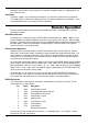
RS232 Anschluss Der 9-polige Steckverbinder (Typ D) für die serielle Schnittstelle befindet sich auf der Geräterückseite. Stiftbelegung: Pin Bez. Beschreibung 1 2 3 4 5 6 7 8 9 DCD TXD RXD DTR GND DSR RTS CTS - Mit Pin 4 und 6 verbunden Vom Gerät übertragene Daten Vom Gerät empfangene Daten Mit Pin 1 und 6 verbunden Betriebserde Mit Pin 1 und 4 verbunden Mit Pin 8 verbunden Mit Pin 7 verbunden Keine Verbindung Zum Anschluss an einen PC werden lediglich die Stifte 2, 3 und 5 benötigt.
Fernbedienungsbefehle RS232 Format der Fernbedienungsbefehle Der Eingabepuffer des Geräts akzeptiert jeweils einen einzelnen Befehl (bzw. Abfrage). Dies erfolgt unter Verwendung eines Interrupts, quasi im Hintergrund und unabhängig zu allen anderen Gerätefunktionen. Befehle und Abfragen müssen entsprechend der Befehlsliste gesendet und mit dem Befehlsschlusszeichen „0AH“ (Line Feed, LF) abgeschlossen werden. Die Parameter müssen durch ein Leerzeichen (20H) vom eigentlichen Befehl getrennt werden.
Rückmeldungsbefehle V? Rückmeldung der gesetzten Ausgangsspannung in Volt (numerisches Format). Die Antwort ist V Beispiel: I? Rückmeldung der Ausgangsstrombegrenzung in Ampere (numerisches Format). Die Antwort ist I Beispiel: VO? Wurde die Strombegrenzung auf 1,00 Ampere gesetzt, so lautet die Antwort auf den Befehl I? I 1.00. Rückmeldung der tatsächlichen Ausgangsspannung in Volt (numerisches Format).
Wartung Die Hersteller bzw. deren Vertretungen im Ausland bieten die Reparatur von Geräten an, bei denen eine Störung aufgetreten ist. Wenn der Eigentümer die Wartungsarbeiten selbst durchführen möchte, hat er dafür Sorge zu tragen, daß diese Arbeiten ausschließlich von entsprechend qualifiziertem Personal und gemäß Wartungshandbuch ausgeführt werden, das direkt von den Herstellern oder deren Vertretungen im Ausland bezogen werden kann.
Sicurezza Questo strumento appartiene alla Categoria di Sicurezza 1, secondo la classifica IEC, ed è stato progettato in modo da soddisfare i criteri EN61010-1 (requisiti di Sicurezza per Apparecchiature di misura, controllo e per uso in laboratorio). È uno strumento di Categoria d’installazione II ed è inteso per il funzionamento con un’alimentazione normale monofase. Questo strumento ha superato le prove previste da EN61010-1 e viene fornito in uno stato di sicurezza normale.
Installazione Tensione d’esercizio Controllare che la tensione d’esercizio dello strumento segnata sul pannello posteriore sia uguale a quella della rete elettrica locale. Cavo d’alimentazione Quando viene fornito un cavo a tre fili con le estremità nude, collegare come segue: MARRONE LINEA BLU NEUTRO VERDE/GIALLO TERRA Simbolo di sicurezza - TERRA. Quando si collega una spina dotata di portafusibile, in essa bisogna inserire un fusibile da 5A.
Funzionamento Impostazione dell’uscita Con l’interruttore POWER (alimentazione) regolato su (l) e l’uscita su off (spenta), la tensione di uscita ed il limite di corrente possono essere preimpostati accuratamente usando i comandi VOLTAGE (tensione) e CURRENT (corrente); il misuratore di sinistra mostra la tensione impostata mentre quello di destra indica la corrente massima impostata.
dell’impostazione più alta immediatamente inferiore e così via. In modalità di corrente costante, vari gruppi possono essere collegati in parallelo per erogare una corrente uguale alla somma dei limiti di corrente impostati. È da notare che i morsetti d’uscita hanno una portata nominale massima di 15A; se si fanno funzionare diverse uscite in parallelo per erogare correnti più alte di questo limite, il collegamento deve essere fatto a un terminale separato e non su uno dei morsetti.
Connettore interfaccia seriale RS232 Il connettore d'interfaccia seriale a vaschetta e 9 pin si trova sul pannello posteriore dello strumento. I collegamenti dei pin sono indicati nella tabella qui sotto: Pin Denom.
Comandi remoti Formato dei comandi remoti RS232 La memoria di transito destinata alla memorizzazione dei dati ricevuti dallo strumento è in grado di accettare un singolo comando (o richiesta di informazioni) per volta, durante l'interrupt, senza interferire con le operazioni eseguite dallo strumento. I comandi e le richieste di informazioni devono essere inviate come prevede l'elenco comandi e devono contenere il codice finale del comando 0AH (interlinea, LF).
Comandi ritorno dati V? Ritorna la tensione erogata impostata in Volt nel formato numerico . La sintassi della risposta è: V Esempio: I? Se la tensione erogata impostata è 12,55 Volt, la risposta al comando V? sarà V 12.55. Ritorna il valore massimo di corrente erogata in Ampere nel formato numerico . La sintassi della risposta è: I Esempio: VO? Se il valore massimo di corrente è impostato su 1,00 Ampere, la risposta al comando I? sarà I 1.00.
Manutenzione I Produttori o i loro agenti all’estero faranno le riparazioni necessarie in caso di guasto. Qualora l’utente desiderasse eseguire il lavoro di manutenzione, tale lavoro deve essere fatto solo da personale qualificato e usando il manuale di servizio che può essere acquistato direttamente dai Produttori o dai loro agenti all’estero. Fusibile Il tipo di fusibile corretto è: 10 Amp 250V ritardato (T) HBC, 5 x 20mm.
Seguridad Este es un instrumento de Clase de Seguridad I según la clasificación del IEC y ha sido diseñado para cumplir con los requisitos del EN61010-1 (Requisitos de Seguridad para Equipos Eléctricos para la Medición, Control y Uso en Laboratorio). Es un instrumento de Categoría de Instalación II propuesto para ser usado con un suministro monofásico normal. Este instrumento ha sido comprobado según la norma EN61010-1 y ha sido suministrado en una condición segura.
Instalación Tensión de la Red Eléctrica Verificar que la tensión de funcionamiento del instrumento que figura en el panel trasero concuerde con el suministro local. Cable de Red Cuando se suministra un cable de tres conductores con puntas peladas, se deberá conectar como sigue: MARRON - CORRIENTE DE RED AZUL - NEUTRO DE RED VERDE/AMARILLO - TIERRA Símbolo de Seguridad de Tierra Cuando se instale un enchufe fusibleado, el enchufe debe llevar un fusible de 5 amp.
Operación Ajuste de la Salida Con el interruptor POWER conectado (l) y se pueden preajustar la salida de la tensión de salida y el límite de corriente con precisión usando los controles de VOLTAGE y CURRENT; el medidor a la izquierda indica la tensión ajustada y el medidor a la derecha indica la corriente máxima preajustada.
La unidad puede conectarse en paralelo a otras para producir una corriente superior. Cuando varias unidades están conectadas en paralelo, el voltaje de salida será igual al de la unidad con el reglaje voltaje de salida superior hasta que la corriente suministrada supere el límite de corriente fijado, lo que resultará en la salida bajando al mayor límite siguiente fijado, y así sucesivamente.
Conector RS232 El conector en serie de tipo D de 9 clavijas de la interfaz se encuentra en la parte trasera del instrumento.
Comandos remotos Formato de los Comandos Remotos de RS232 La memoria intermedia de entrada del instrumento acepta un solo comando individual (o pregunta) al mismo tiempo, bajo interrupción, de forma transparente a las demás operaciones del instrumento. Los comandos y las preguntas se deben enviar de la forma especificada en la lista de comandos y deben finalizar con el código de finalización de comandos 0AH (Avance de línea, LF).
Comandos de lectura de comprobación V? Devuelve el voltaje de salida ajustado en voltios, en formato numérico . La sintaxis de la respuesta es V Ejemplo: I? Si el voltaje de salida ajustado es 12,55 voltios, la respuesta al comando V? será V 12.55. Devuelve el límite de corriente de salida en amperios en formato numérico . La sintaxis de la respuesta es I Ejemplo: VO? Si el límite de corriente es 1.00 amperios, la respuesta al comando I? será I 1.00.
Mantenimiento Los fabricantes o sus agentes en el extranjero ofrecen un servicio de reparación para toda unidad que desarrolle un defecto. Si los propietarios desearan establecer su propio servicio, esto sólo debe realizarse por personas cualificadas en conjunto con el manual de servicio que puede adquirirse directamente del Fabricante o de sus agentes en el extranjero. Fusible El tipo correcto del fusible es: 10 Amperios 250V HBC retardo(T), 5 x 20mm.
Book Part No.