
Installation Guide


BATHROOM FAN
www.aeropurefans.com
MODEL: VSF110DMH-S
WARNING
WARNING -TO REDUCE THE RISK OF FIRE, ELECTRIC SHOCK, OR INJURY TO PERSONS, PLEASE READ
THE FOLLOWING PRIOR TO INSTALLING THE FAN:
1. Use this unit only in the manner intended by the manufacturer. If you have questions, contact the manufacturer. 2. Before
servicing or cleaning unit, switch power off at service panel to prevent power from being switched on accidentally. When the service
disconnect cannot be locked, securely fasten a prominent warning device, such as a tag, to the service panel. 3. Installation work
and electrical wiring must be done by a licensed person(s) in accordance with all applicable codes and standards, including fire-rated
construction codes and standards. 4. Sufficient air is needed for proper combustion and exhausting of gases through the flue
(chimney) of fuel burning equipment to prevent backdraft. Follow the heating equipment manufacturer’s guideline and safety
standards such as those published by the National Fire Protection Association (NFPA), and the American Society for Heating,
Refrigeration and Air Conditioning Engineers (ASHRAE), and the local code authorities. 5. When cutting or drilling into wall or ceiling,
do not damage electrical wiring and other hidden utilities. 6. Ducted fans must always be vented to the outdoors. 7. Unit is
acceptable for use over a tub or shower when connected to a GFCI (Ground Fault Circuit Interrupter) protected branch circuit (ceiling
installation only). 8. This unit must be grounded. 9. Not for use in kitchens. 10. Install fan at least 2.5 m (8.2 feet) above the floor.
11. To reduce risk of fire and to properly exhaust air, be sure to duct air outside. Do not vent exhaust air into spaces within walls or
ceilings or into attics, crawl spaces, or garages. This unit is appropriate for wall installation in a non-wet application. 12. WARNING:
To reduce the risk of fire or electric shock, do not use this fan with any solid-state speed control device. 13. The fan must not be
installed in a ceiling thermally insulated to a value greater than R40.
CAUTION
1. For general ventilating use only. Do not use to exhaust hazardous or explosive materials and vapors. 2. This product is designed for
installation in ceilings up to a 12/12 pitch (45 degree angle). Duct connector must point upward for wall application. 3. To avoid motor
bearing damage and noisy and/or unbalanced impellers, keep drywall spray, construction dust, etc. off power unit. 4. Please read
specification label on product for further information and requirements.
*This manual in electronic format may be downloaded from our company website or obtained from the dealer.
CLEANING & MAINTENANCE
For quiet and efficient operation, long life, and attractive appearance - lower or remove grille and vacuum interior of unit with the dusting
brush attachment.
The motor is permanently lubricated and never needs oiling.
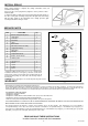
OPERATION
Power box
The control box, located inside the fan housing, has three separate
adjustments:
Toggle switch
(1) The time delay knob which is adjustable from 5 to 60 minutes and switches the
humidity sensor knob.
Humidity
Sensor knob
12 3
+
+
(2) The humidity sensor for setting the proper relative humidity level in the room.
Switch
(3) The toggle switch will adjust the upper fan speed setting from 80 to 120 CFM
using a 4” duct or 90 to 140 CFM using a 6” duct.
position
1 2 3
1 2 3
1 2 3
1
2
3
1 2 3
1 2 3
1 2 3
1 2 3
Air deliver (CFM)
80
90
110 120
90
110
120
140
1 2 3
Duct
diameter (inches)
4"
4"
4"
4"
6"
6"
6"
6"
Both 4" and 6" duct adaptors are included.
is the position of switch
Times of operation:
(a) When someone enters then leaves the room.
(b) When humidity rises above a user-adjustable set point (50-100% Relative
Humidity (RH)).
Switch
position
1 2 3
1 2 3
1 2 3
1 2 3
1 2 3
1 2 3
1 2 3
1 2 3
Airflow
Duct
diameter
4"
4"
4"
4"
6"
6"
6"
6"
(inches)
Factory setting: 110CFM ( ) with 6" duct
HVI Certified performance based on HVI Procedures 915,
916, and 920.
Other airflow reference performance based on HVI
Procedures 915, 916, and 920.
READ AND SAVE THESE INSTRUCTIONS
Installer: Leave this manual with the homeowner.
1
Timer
delay knob