
Specifications


15
© 2012 Emerson Climate Technologies, Inc.
Printed in the U.S.A.
AE8-1368 R2
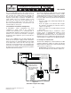
3. Press F5 (Setup)
4. Press F2 (Next Tab)
The E2 screen should look like Figure 4.11
Demand Cooling control is provided by the Unloader
2 solenoid output. Setting the Unloader 2 value to
Demand Cooling will allow the Demand Cooling valve
to be cycled properly based on the compressor head
temperature.
4.10 Crankcase Heater Control
The parameter labeled ISD CCH control determines
whether the heater is to be controlled by the module
or by an external means such as an auxiliary contact.
Setting this value to “enabled” allows the heater to be
controlled by the CoreSense Diagnostics module.
The parameter labeled Crankcase Algorithm determines
how the CoreSense Diagnostics module will control
the switching of the heater. With this parameter set to
continuous, the heater will be activated any time that
the compressor is OFF. This operation is the same
as if the heater were controlled by a set of auxiliary
contacts
4.11 Anti Short Cycle
The parameter labeled Anti Short Cycle determines
the minimum off time for compressors before they
restart. This value is set to reduce the number of start/
stop cycles on the compressor. The default value is 0.1
minutes or 6 seconds. This value may be set from 0.1
to 2 minutes.
4.12 MCC Value
The parameter labeled MCC Value is the maximum
continuous current for the compressor. This value
is set to provide additional motor protection for the
compressor. This value is programmed based upon
the current requirements of each compressor model.
(For dual voltage motors, the MCC value will be set to
the 460 volt value. If the compressor is run at a different
voltage the MCC value may be adjusted accordingly).
4.13 Compressor Voltage
The value for compressor voltage is preloaded at the
factory. If the compressor is to be operated at a voltage
other than the value listed, the proper voltage must be
entered into this fi eld.
4.14 Compressor Frequency
The value for compressor frequency is preloaded at
the factory. If the compressor is to be operated at a
frequency other than the value listed, the proper
frequency must be entered into this fi eld.
language
voltage imbalance
demand cooling
4.8 Unloader Confi guration
The unloader confi guration settings are preloaded
at the factory and will match the requirements of the
compressor. The Unloader Mod Type setting of Digital
is for digital unloading only. For compressors without
unloaders or for those with non-digital unloading
(blocked suction) the Unloader Mod Type should be
set to None.
For proper operation when in the Digital Modulation
mode, the number of banks (Bank Confi g) must
be correct. 3D compressors have one bank, 4D
compressors have two banks and 6D compressors
have three banks.
If this confi guration is changed in the fi eld (for
example to add Digital Modulation as a fi eld upgrade),
please follow these steps to confi gure the suction
group and the compressor associations:
Amend the number of stages in the suction group
if necessary (see section 4.3). Then, change the
compressor associations as follows:
1. From the main menu select 7 (System
Confi guration)
2. Press 7 (Network Setup)
3. Press 4 (Controller Associations)
4. Press 4 (Compressor)
Referring to Figure 4.9 (section 4.4), delete the
suction group association and set the stages to
“zero” for this compressor. Stair-step out. Next, re-
enter the association screen and re-establish the
suction group and the proper stage number. Note:
for a digital compressor, the compressor (regardless
of the number of unloaders) will be just one stage.
Re-establishing the association is done to allow the
suction group to see that the compressor is now a
Digital compressor (or is no longer a digital, as the
case may be).
4.9 Demand Cooling Confi guration
Demand Cooling confi guration settings are preloaded
at the factory and will match the requirements of the
compressor. To verify the settings or to enable demand
cooling follow these steps:
1. From the main menu select 5 (Confi gured
Applications)
2. Press 104 (ISD 2.0)