
User Manual


10
Dry Contact Option
The XGA Series is available with optional Dry Contacts
which utilize a DB-9 connector. This feature provides two
sets of normally open (N.O.) and normally closed (N.C.)
contacts through the DB-9 connector. These relay contacts
can be used for remote indication of the SPD’s operating
status. Examples could include a computer interface
board, an emergency management system, etc. The relay
contact pin arrangement is outlined in Table 2. (Please
note the jumpered connections. Pins 7, 8 & 9 were used
to drive an earlier version of the Remote Monitor option.
Pins 7, 8 & 9 do not represent a third set of contacts. Pin
pairs 4 & 7, 5 & 8, and 6 & 9, are connected via jumper
internally. The combined current of each pin pair may not
exceed 1 Ampere).
An optional Remote Monitor accessory is available that
will provide visual and audible indication of an alarm
condition. The Remote Monitor requires the Dry Contact
option as it collects information through the Dry Contact’s
DB-9 connection. Please note that the DB-9 connector
is completely utilized by the optional remote monitoring
accessory. If the Remote Monitor is used, there will be no
means to interface with another device.
For custom applications using the Dry Contacts, please
note the following information:
• The Dry Contacts are designed for low voltage or
control signals only.
• Maximum switching current is 1 amp.
• Maximum switching voltage is 24 volts, DC or AC.
Higher energy application may require additional relay
implementation outside the SPD. Damage to the SPD’s
relay caused by implementation with energy levels in
excess of those discussed in this manual will not be
covered by warranty. If you have design questions, please
contact APT Technical Support at: 1.800.237.4567.
Remote Monitor Accessory Option
A Remote Monitor is available for remote annunciation.
It requires a standalone 120V power source (wall plug
transformer) and uses one set of Form C dry contacts. The
Remote Monitor can be congured to monitor several APT
SPDs simultaneously. Installation is detailed in a separate
document. Contact factory as appropriate.
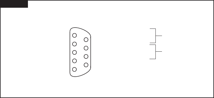
Figure 16
PINOUT DIAGRAM FOR DRY CONTACTS OF SPD
Using DB-9
Syle Connector:
1 Normally Closed
2 Common
3 Normally Open
4 Normally Closed
5 Common
6 Normally Open
7 Connected to Pin 4
8 Connected to Pin 5
9 Connected to Pin 6
1
2
3
4
5
6
7
8
9
Form C Set #2
Form C Set #1
MAINTENANCE
SPDs require minimal maintenance. We recommend
periodic inspection of diagnostic indicators to ensure
proper operation. We also recommend keeping the SPD
clean as appropriate.
Troubleshooting & Service
Please contact us for any service related issues. We want
to take care of any problems.
Quality SPDs are designed and tested to withstand severe
duty. However, there are various electrical anomalies that
SPDs cannot protect against. These are generally Sustained
Overvoltages also known as Temporary Overvoltages
(TOVs). In this context, Sustained Overvoltages may be
only a few cycles. Failed SPDs tend to be symptoms, not
root causes. A failed SPD should be treated as a ‘canary
in the coalmine’ suggesting further investigation as there
may be a larger issue at play. Regardless of cause, SPDs
attempt to protect their load until failure.
As noted above, the single largest ‘killer’ of SPDs is
reference to ground issues. If the SPD shows problems on
startup, there is reasonable chance of bonding/grounding/
misapplication issue. This permanently damages the unit.
If not corrected, it will happen again.
Tip: Visually conrm N-G bonding. Be aware that a voltmeter measuring
N-G can be misleading. For example, N-G voltage could read 0V
because neutral and ground are at the same potential purely by
happenstance, not because they are bonded. Visually conrm bonding.
Tip: Experience indicates that regulation-challenged generators can
cause Sustained Overvoltages, as well as ungrounded generators, and/
or unusual load transfer systems.
Note: Prior to returning power or servicing the SPD, inspect
the entire SPD for any other damaged components. Any
damaged components should be replaced prior to returning
the SPD to service.
1 Normally Closed
2 Common
3 Normally Open
4 Normally Closed
5 Common
6 Normally Open
7 Connected to Pin 4
8 Connected to Pin 5
9 Connected to Pin 6
1
2
3
4
5
6
7
8
9
Form C Set #2
Form C Set #1