
User's Manual

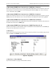


Table Of Contents
- Table of Contents
- System Description
- Microwave Path Engineering Basics
- Engineering Guidelines
- Network Turnup Procedure
- User Interface Guide
- 1. Navigating the Terminal Menu
- 2. Menu and System Control
- 3. Menu Descriptions
- > System Status
- > Main Menu
- > System Configuration
- > RF Link Configuration
- > RF Link Performance History (Main Screen)
- > RF Link Error History
- > RF Link Max/Min Received Power History
- > RF Link Min/Max Received Signal Quality History
- > Datapath Provisioning
- > 4xE1 Module Configuration/Status/History (Main Screen)
- > E1x Status/Configuration/Loopback
- > E1x Performance History
- > T1 Module Configuration/Status/History (Main Screen)
- > T1x Status/Configuration/Loopback
- > Ethernet Switch Module Configuration/Status/History (Main Screen)
- > Ethernet Switch Configuration
- > Ethernet Switch Status
- > Management/Utilities (Main Screen)
- > Ping Utility
- > Firmware Upgrade Utility
- > RF Link Management Bridge Configuration
- > System Alarms
- Detail Level Procedures
- MIBs
- Troubleshooting Guide
- 1. Overview
- 2. LED Indicators
- PWR LED
- TST LED
- RF DWN LED
- RF LOW LED
- T1 Interface Alarms
- E1 Interface Alarms
- 1. Display the E1(x) Status screen and check the E1(x) Interface Alarm field to identify the active alarm.
- 1. Verify that the E1 cable is connected to the E1 interface on the TRACER 64x0.
- 2. Verify the connections at the opposite end of the E1 cable.
- 3. Verify that the framing mode (framed, multiframed, or unframed) is the same for both the TRACER 64x0 and the E1 equipment.
- 2. Verify the cable connections for the E1 interface are solid.
- 2. Verify the cable connections for the E1 interface are solid.
- LAN LEDs
- 3. RF Errors
- 4. Step-by-Step Troubleshooting
- 5. Installing/Troubleshooting the TRACER Hardware

TRACER 6000 Series Integrated System Manual Section 5 User Interface Guide
612806420L1-1D Copyright © 2005 ADTRAN, Inc. 87
> FIRMWARE UPGRADE UTILITY > UPGRADE DESTINATION
Specify the unit to upgrade. The following options are available:
> FIRMWARE UPGRADE UTILITY > COMMAND
Use this command to start (START) or stop (ABORT) a firmware upgrade. For XMODEM updates, cancel
the process via the terminal emulation software (consult your documentation for instructions on how to do
this). For TFTP updates, you can cancel the process by selecting
ABORT from this field.
> FIRMWARE UPGRADE UTILITY > LOCAL CURRENT STATUS
(Available for TFTP updates only.) Indicates progress or problems encountered during the current upgrade
of the local unit. The field displays
IDLE if no update is in progress or when the update is successfully
completed. At the end of a successful update, the contents of this field are copied into the Local Previous
Status. For a detailed listing of these messages, please refer to DLP-5, Updating the Firmware Using
TFTP, on page 103.
> FIRMWARE UPGRADE UTILITY > LOCAL PREVIOUS STATUS
(Available for TFTP updates only.) Displays the status of the previous update of the local unit. Following a
successful update, this field reads
UPGRADE FINISHED SUCCESSFULLY. If an update was unsuccessful, the
appropriate error message displays. Refer to DLP-5, Updating the Firmware Using TFTP, on page 103 for
more details on available error messages.
> FIRMWARE UPGRADE UTILITY > REMOTE CURRENT STATUS
(Available for TFTP updates only.) Indicates progress or problems encountered during the current upgrade
of the remote unit. The field displays
IDLE if no update is in progress or when the update is successfully
completed. At the end of a successful update, the contents of this field are copied into the Local Previous
Status. For a detailed listing of these messages, please refer to DLP-5, Updating the Firmware Using
TFTP, on page 103.
> FIRMWARE UPGRADE UTILITY > REMOTE PREVIOUS STATUS
(Available for TFTP updates only.) Displays the status of the previous update of the remote unit. Following
a successful update, this field reads
UPGRADE FINISHED SUCCESSFULLY. If an update was unsuccessful, the
appropriate error message displays. Refer to DLP-5, Updating the Firmware Using TFTP, on page 103 for
more details on available error messages.
LOCAL IDU
Upgrade the local system.
REMOTE IDU
Upgrade the remote system. When upgrading the remote system, the
upgrade file is first loaded into the local system and then transferred
over the wireless link to the remote system. The actual upgrade
process is not started on the remote system until the entire upgrade
file has been received.