
User's Manual Part 1


ADCP-75-348 • Issue 1 • 04/2008
Page 24
© 2008, ADC Telecommunications, Inc.
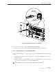
6.12 System Alarm System Connections
The alarm interface between the HU and an alarm system is supported by twelve-terminal plug
(with screw-type terminals) that connects to a receptacle mounted on the HU System card front
panel. The terminal plug provides connections to normally open (NO) and normally closed
(NC) dry type alarm contacts for both major and minor alarms. A category 3 or 5 cable is
typically used to connect the HU System card to the alarm system. Use the following procedure
to install the alarm wiring and connect it to the HU:
1. Obtain the required length of category 3 or 5 cable.
2. Route the cable between the HU System card and the alarm system (if not already routed)
and then cut to the required length. Allow sufficient slack for dressing and organizing the
cable at the HU.
3. Strip back the outer cable sheath and insulation to expose the wires at both ends of the
cable and strip back 0.2 inches (5 mm) of insulation from each wire.
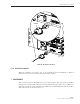
4. Connect the Major alarm wire pair to the MAJOR COM/NC or MAJOR COM/NO
terminals (whichever is required by the alarm system) on the HU System card alarm
terminal connector (supplied with HU System card) as shown in Figure 18.
5. Connect the Minor alarm wire pair to the MINOR COM/NC or MINOR COM/NO
terminals (whichever is required by the alarm system) on the HU System card alarm
terminal connector (see Figure 18 and Table 4).
6. Connect the Major and Minor alarm wire pairs to the appropriate terminals on the external
alarm system.
7. Dress and secure cable per standard industry practice.
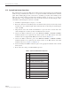
Table 4. System Card Alarm Pin Designations
PIN DESCRIPTION
1 Host Minor Normally Closed
2 Host Minor Common
3 Host Minor Normally Open
4 Host Major Normally Closed
5 Host Major Common
6 Host Major Normally Open
7 Remote Minor Normally Closed
8 Remote Minor Common
9 Remote Minor Normally Open
10 Remote Major Normally Closed
11 Remote Major Common
12 Remote Major Normally Open