
User's Manual


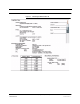


Table Of Contents
- SECTION 1 General Information
- SECTION 2 InterReach Fusion System Description
- SECTION 3 Fusion Main Hub
- SECTION 4 Fusion Expansion Hub
- SECTION 5 Remote Access Unit
- SECTION 6 Designing a Fusion Solution
- 6.1 Overview
- 6.2 Downlink RSSI Design Goal
- 6.3 Maximum Output Power per Carrier
- 6.3.2 700 MHz (Upper C)
- 6.4 System Gain
- 6.5 Estimating RF Coverage
- 6.6 Link Budget Analysis
- 6.6.1 Elements of a Link Budget for Narrowband Standards
- 6.7 Optical Power Budget
- 6.8 Connecting a Main Hub to a Base Station
- 6.8.1 Uplink Attenuation
- 6.8.2 RAU Attenuation and ALC
- SECTION 7 Installing Fusion
- 7.1 Installation Requirements
- 7.1.2 Cable and Connector Requirements
- 7.1.3 Distance Requirements
- 7.2 Safety Precautions
- 7.2.1 Installation Guidelines
- 7.2.2 General Safety Precautions
- 7.2.3 Fiber Port Safety Precautions
- 7.3 Preparing for System Installation
- 7.3.1 Pre-Installation Inspection
- 7.3.2 Installation Checklist
- 7.3.3 Tools and Materials Required
- 7.3.4 Optional Accessories
- 7.4 Fusion Installation Procedures
- 7.4.1 Installing a Fusion Main Hub
- 7.4.3 Installing RAUs
- 7.4.4 Configuring the System
- 7.5 Splicing Fiber Optic Cable
- 7.6 Interfacing the Fusion Main Hub to an RF Source
- 7.6.1 Connecting a Single Fusion Main Hub to an RF Source
- 7.7 Connecting Contact Alarms to a Fusion System
- 7.8 Alarm Monitoring Connectivity Options
- 7.8.1 Direct Connection
- 7.8.5 Ethernet RF Modem
- SECTION 8 Replacing Fusion Components
- SECTION 9 Maintenance, Troubleshooting, and Technical Assistance
- APPENDIX A Cables and Connectors
- APPENDIX B Compliance
- APPENDIX C Faults, Warnings, Status Tables for Fusion, Fusion Wideband, Fusion SingleStar

InterReach Fusion Installation, Operation, and Reference Manual A-1
D-620610-0-20 Rev F CONFIDENTIAL
APPENDIX A Cables and Connectors
A.1 75 Ohm CATV Cable
• Connects the Expansion Hub to the RAU(s)
• Transmits multiband (downlink) and receives (uplink) IF signals
• Delivers DC electrical power to the RAUs. The Fusion Hub’s DC voltage output is
54V DC nominal. A current limiting circuit is used to protect the Hub if it reaches
its current limit
• Carries configuration and status information
• Use 75 Ohm type-F connectors with captive centerpins
• Lengths:
RG-59:
• Minimum: 0 meters (0 ft.)
• Maximum: 150 meters (492 ft.)
RG-6:
• Minimum: 0 meters (0 ft.)
• Maximum: 170 meters (558 ft.)
RG-11:
• Minimum: 0 meters (0 ft.)
• Maximum: 275 meters (902 ft.)
Recommended minimum and maximum CATV cable lengths vary depending upon
which CATV cable you use.
Be sure to test cable termination before installing the cable.
CommScope CATV cable or equivalent is required:
CommScope 20655V for RG-59. This cable is illustrated in Figure A-1.
CommScope 2279V for RG-6. This cable is illustrated in Figure A-2.
CommScope 2293K for RG-11.This cable is illustrated in Figure A-3.