
User's Manual


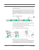


Table Of Contents
- SECTION 1 General Information
- SECTION 2 InterReach Fusion System Description
- SECTION 3 Fusion Main Hub
- SECTION 4 Fusion Expansion Hub
- SECTION 5 Remote Access Unit
- SECTION 6 Designing a Fusion Solution
- 6.1 Overview
- 6.2 Downlink RSSI Design Goal
- 6.3 Maximum Output Power per Carrier
- 6.3.2 850 MHz Cellular
- 6.4 System Gain
- 6.5 Estimating RF Coverage
- 6.6 Link Budget Analysis
- 6.6.1 Elements of a Link Budget for Narrowband Standards
- 6.7 Optical Power Budget
- 6.8 Connecting a Main Hub to a Base Station
- 6.8.1 Uplink Attenuation
- 6.8.2 RAU Attenuation and ALC
- SECTION 7 Installing Fusion
- 7.1 Installation Requirements
- 7.1.2 Cable and Connector Requirements
- 7.1.3 Distance Requirements
- 7.2 Safety Precautions
- 7.2.1 Installation Guidelines
- 7.2.2 General Safety Precautions
- 7.2.3 Fiber Port Safety Precautions
- 7.3 Preparing for System Installation
- 7.3.1 Pre-Installation Inspection
- 7.3.2 Installation Checklist
- 7.3.3 Tools and Materials Required
- 7.3.4 Optional Accessories
- 7.4 Fusion Installation Procedures
- 7.4.1 Installing a Fusion Main Hub
- 7.4.3 Installing RAUs
- 7.4.4 Configuring the System
- 7.5 Splicing Fiber Optic Cable
- 7.6 Interfacing the Fusion Main Hub to an RF Source
- 7.6.1 Connecting a Single Fusion Main Hub to an RF Source
- 7.7 Connecting Contact Alarms to a Fusion System
- 7.8 Alarm Monitoring Connectivity Options
- 7.8.1 Direct Connection
- 7.8.5 Ethernet RF Modem
- SECTION 8 Replacing Fusion Components
- SECTION 9 Maintenance, Troubleshooting, and Technical Assistance
- APPENDIX A Cables and Connectors
- APPENDIX B Compliance
- APPENDIX C Faults, Warnings, Status Tables for Fusion, Fusion Wideband, Fusion SingleStar

Help Hot Line (U.S. only): 1-800-530-9960 7-33
D-620610-0-20 Rev E CONFIDENTIAL
Fusion Installation Procedures
these situations is to provide sufficient isolation by physically separating the interfer-
ing transmitters and receivers.
iDEN occupies spectrum at both 800 MHz and 900 MHz (Tx:851–869/Rx:806–824
and Tx:935–941/Rx:896–902), while the Cellular A and B carriers share a single 850
MHz block (Tx:869–894/Rx:824–849). The combination of these frequency bands,
800/900 MHz iDEN and 850 MHz Cellular, result in uplink (BTS receive) bands that
are adjacent to downlink (BTS transmit) bands. Figure 7-19 depicts these nearly con-
tiguous bands, with arrows indicating the interfering downlink and receiving uplink
bands.
Figure 7-19 800/850 MHz Spectrum
Installation of an in-building distributed antenna system (DAS) to provide coverage
for both 800/900 MHz iDEN and 850 MHz Cellular must account for these down-
link-to-uplink interference issues and provide adequate isolation.
ADC offers the following guidelines toward achieving the proper amount of isolation
when deploying ADC Fusion DAS products.
Figure 7-20 Guideline for Unison RAU Antenna Placement
800 MHz iDEN Downlink and 850 MHz Cellular Uplink
A 2 MHz frequency gap (851 – 849 MHz) separates the 800 iDEN downlink and 850
Cellular uplink frequency bands. Because of this narrow spacing, 800 iDEN down-
link intermodulation products may fall within the 850 Cellular uplink band. In addi-
tion, 800 iDEN downlink signals near the lower edge of the band at 851 MHz may
850
850
896-902
850
Cellular
MHub
FSN-809019-2 RAU
FSN-8519-1 RAU
850
Cellular
RAU
850
EHub
Cellular