
User's Manual
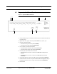


Table Of Contents
- SECTION 1 General Information
- SECTION 2 InterReach Fusion Wideband System Description
- SECTION 3 Fusion Wideband Main Hub
- SECTION 4 Fusion Wideband Expansion Hub
- SECTION 5 Remote Access Unit
- SECTION 6 Designing a Fusion Wideband Solution
- SECTION 7 Installing Fusion Wideband
- 7.1 Installation Requirements
- 7.2 Safety Precautions
- 7.3 Preparing for System Installation
- 7.4 Fusion Wideband Installation Procedures
- 7.5 Splicing Fiber Optic Cable
- 7.6 Interfacing the Fusion Wideband Main Hub to an RF Source
- 7.7 Connecting Contact Alarms to a Fusion Wideband System
- 7.8 Alarm Monitoring Connectivity Options
- SECTION 8 Replacing Fusion Wideband Components
- SECTION 9 Maintenance, Troubleshooting, and Technical Assistance
- APPENDIX A Cables and Connectors
- A.1 75 Ohm CATV Cable
- A.2 Fiber Optical Cables
- A.3 Coaxial Cable
- A.4 Standard Modem Cable
- A.5 TCP/IP Cross-over Cable
- A.6 DB-9 to DB-9 Null Modem Cable
- APPENDIX B Compliance
- B.1 Fusion Wideband System Approval Status
- B.2 Human Exposure to RF
- APPENDIX C Faults, Warnings, Status Tables for Fusion, Fusion Wideband, Fusion SingleStar
- C.1 Faults Reported by Main Hubs
- C.2 Faults Reported for System CPU
- C.3 Faults for Expansion Hubs
- C.4 Faults for RAUs
- C.5 Messages for Main Hubs
- C.6 Messages for System CPUs
- C.7 Messages for Expansion Hubs
- C.8 Messages for RAUs

Expansion Hub Front Panel
4-4 InterReach Fusion Wideband Installation, Operation, and Reference Manual
CONFIDENTIAL D-620616-0-20 Rev D
4.2.1 75 Ohm Type F Connectors
The eight type F connectors on the Expansion Hub are for the CATV cables used to
transmit and receive signals to and from RAUs. Use only 75 ohm type F connectors
on the CATV cable.
The CATV cable also delivers DC electrical power to the RAUs. The Expansion
Hub’s DC voltage output is 54V DC nominal. A current limiting circuit protects the
Hub if any port draws excessive power.
NOTE: For system performance, it is important to use only low loss solid cop-
per center conductor CATV cable with quality type F connectors that use captive
centerpin connectors. Refer to Appendix A for approved cables and connectors.
4.2.2 Manufacturing RS-232 Serial Connector
Console Port
This console port is only used by ADC manufacturing test purposes. DO NOT CON-
NECT ANYTHING TO IT.
Local Monitoring
Use a crossover Ethernet cable (PN-4069-ADB) to directly connect a laptop or PC to
the RJ-45 female connector for local monitoring or configuring the Expansion Hub
and associated RAUs using the AdminBrowser-EH resident software. The cable typi-
cally has a RJ-45 male connector on both ends. Refer to Appendix A.5 on page A-8
for the cable pinout and the AdminBrowser manual.
4.2.3 Optical Fiber Uplink/Downlink Connectors
The optical fiber uplink/downlink port transmits and receives optical signals between
the Expansion Hub and the Main Hub using industry-standard SMF or MMF cable.
The fiber port has two female SC/APC connectors:
• Optical Fiber Uplink Connector
This connector (labeled
UPLINK) is used to transmit (output) uplink optical signals
to the Main Hub.
• Optical Fiber Downlink Connector
This connector (labeled
DOWNLINK) is used to receive (input) downlink optical sig-
nals from the Main Hub.
CAUTION: To avoid damaging the Expansion Hub’s fiber connector
ports, use only SC/APC fiber cable connectors. Additionally, use only