
User's Manual


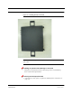


Table Of Contents
- SECTION 1 General Information
- SECTION 2 InterReach Fusion Wideband System Description
- SECTION 3 Fusion Wideband Main Hub
- SECTION 4 Fusion Wideband Expansion Hub
- SECTION 5 Remote Access Unit
- SECTION 6 Designing a Fusion Wideband Solution
- SECTION 7 Installing Fusion Wideband
- 7.1 Installation Requirements
- 7.2 Safety Precautions
- 7.3 Preparing for System Installation
- 7.4 Fusion Wideband Installation Procedures
- 7.5 Splicing Fiber Optic Cable
- 7.6 Interfacing the Fusion Wideband Main Hub to an RF Source
- 7.7 Connecting Contact Alarms to a Fusion Wideband System
- 7.8 Alarm Monitoring Connectivity Options
- SECTION 8 Replacing Fusion Wideband Components
- SECTION 9 Maintenance, Troubleshooting, and Technical Assistance
- APPENDIX A Cables and Connectors
- A.1 75 Ohm CATV Cable
- A.2 Fiber Optical Cables
- A.3 Coaxial Cable
- A.4 Standard Modem Cable
- A.5 TCP/IP Cross-over Cable
- A.6 DB-9 to DB-9 Null Modem Cable
- APPENDIX B Compliance
- B.1 Fusion Wideband System Approval Status
- B.2 Human Exposure to RF
- APPENDIX C Faults, Warnings, Status Tables for Fusion, Fusion Wideband, Fusion SingleStar
- C.1 Faults Reported by Main Hubs
- C.2 Faults Reported for System CPU
- C.3 Faults for Expansion Hubs
- C.4 Faults for RAUs
- C.5 Messages for Main Hubs
- C.6 Messages for System CPUs
- C.7 Messages for Expansion Hubs
- C.8 Messages for RAUs

Help Hot Line (U.S. only): 1-800-530-9960 7-25
D-620616-0-20 Rev D CONFIDENTIAL
Fusion Wideband Installation Procedures
7.4.2 Installing Expansion Hubs
The Expansion Hub (2U high) can be installed in a standard 19 in. (483 mm) equip-
ment rack or in a wall-mountable equipment rack that is available from ADC. Allow
a clearance of 76 mm (3 in.) front and rear and 51 mm (2 in.) sides for air circulation.
No top and bottom clearance is required.
CAUTION: Install Expansion Hubs in indoor locations only.
Installing an Expansion Hub in a Rack
Consideration:
• The Expansion Hub is shipped with #10-32 mounting screws. Another common
rack thread is #12-24. Confirm that the mounting screws match the rack’s threads.
Figure 7-15 Flush Mounting Bracket Detail
To install the hub in a rack:
1. Insert spring nuts into the rack where needed or use existing threaded holes.
2. Place the Expansion Hub into the rack from the front.
3. Align the flange holes with the spring nuts installed in Step 1.
4. Insert the mounting screws in the appropriate positions in the rack.
5. Tighten the mounting screws.