
User's Guide

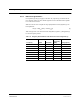


Table Of Contents
- SECTION 1 General Information
- SECTION 2 InterReach Fusion System Description
- SECTION 3 Fusion Main Hub
- SECTION 4 Fusion Expansion Hub
- SECTION 5 Remote Access Unit
- SECTION 6 Designing a Fusion Solution
- SECTION 7 Installing Fusion
- SECTION 8 Replacing Fusion Components
- SECTION 9 Maintenance, Troubleshooting, and Technical Assistance
- APPENDIX A Cables and Connectors
- A.1 75 Ohm CATV Cable
- A.2 Fiber Optical Cables
- A.3 Coaxial Cable
- A.4 Standard Modem Cable
- A.5 TCP/IP Cross-over Cable
- A.6 DB-25 to DB-9 Null Modem Cable
- APPENDIX B Compliance
- B.1 Fusion System Approval Status
- B.2 Human Exposure to RF
- APPENDIX C Faults, Warnings, Status Tables
- C.1 Faults Reported by Fusion Main/SingleStar Hubs
- C.2 Faults Reported for System CPU
- C.3 Faults for Fusion Expansion Hubs
- C.4 Faults for RAUs
- C.5 Warning/Status Messages for Fusion Main/SingleStar Hubs
- C.6 Warning/Status Messages for System CPUs
- C.7 Warning/Status Messages for Fusion Expansion Hubs
- C.8 Warning /Status Messages for RAUs

Help Hot Line (U.S. only): 1-800-530-9960 6-23
D-620610-0-20 Rev B CONFIDENTIAL
Estimating RF Coverage
Example Design Estimate for an 1900 MHz CDMA Application
1. Design goals:
• PCS (1920 MHz = average of the lowest uplink and the highest downlink fre-
quency in 1900 MHz PCS band)
•CDMA provider
• 8 CDMA carriers in the system
• –85 dBm design goal (to 95% of the building) — the minimum received power
at the wireless device
• Base station with simplex RF connections
2. Power Per Carrier: The tables in Section 6.3, “Maximum Output Power per Car-
rier,” on page 6-4 provide maximum power per carrier information. The 1900
MHz CDMA table (on page 6-9) indicates that Fusion can support eight carriers
with a recommended maximum power per carrier of 6.5 dBm. The input power
should be set to the desired output power minus the system gain.
3. Building information:
• 16 floor building with 9,290 sq. meters (100,000 sq. ft.) per floor; total
148,640 sq. meters (1,600,000 sq. ft.).
• Walls are sheetrock construction, suspended ceiling tiles.
• Antennas used are omni-directional, ceiling mounted.
• Standard office environment, 80% hard wall offices and 20% cubicles.
4. Link Budget: In this example, a design goal of –85 dBm is used. Suppose 3 dBi
omni-directional antennas are used in the design. Then, the maximum RF propa-
gation loss should be no more than 94.5 dB (6.5 dBm + 3 dBi + 85 dBm) over
95% of the area being covered. It is important to note that a design goal such as
–85 dBm is usually derived taking into account multipath fading and log-normal
shadowing characteristics. Thus, this design goal will only be met “on average”
over 95% of the area being covered. At any given point, a fade may bring the sig-
nal level underneath the design goal.
Note that this method of calculating a link budget is only for the downlink path.
For information to calculate link budgets for both the downlink and uplink paths,
refer to Section 6.6 on page 6-25.
5. Path Loss Slope: For a rough estimate, Table 6-11, “Estimated Path Loss Slope for
Different In-Building Environments” on page 6-17, shows that a building with 80%
hard wall offices and 20% cubicles, at 1920 MHz, has an approximate path loss
slope (PLS) of 38.1. Given the RF link budget of 94.5 dB, the distance of coverage
from each RAU will be 30.2 meters (99 ft). This corresponds to a coverage area
of 2,868 sq. meters (30,854 sq. ft.) per RAU (refer to Section 6.5.1 for details on
path loss estimation). For this case we assumed a circular radiation pattern, though
the actual area covered depends upon the pattern of the antenna and the obstructions
in the facility.