
User's Guide


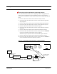


Table Of Contents
- SECTION 1 General Information
- SECTION 2 InterReach Fusion System Description
- SECTION 3 Fusion Main Hub
- SECTION 4 Fusion Expansion Hub
- SECTION 5 Remote Access Unit
- SECTION 6 Designing a Fusion Solution
- SECTION 7 Installing Fusion
- SECTION 8 Replacing Fusion Components
- SECTION 9 Maintenance, Troubleshooting, and Technical Assistance
- APPENDIX A Cables and Connectors
- A.1 75 Ohm CATV Cable
- A.2 Fiber Optical Cables
- A.3 Coaxial Cable
- A.4 Standard Modem Cable
- A.5 TCP/IP Cross-over Cable
- A.6 DB-25 to DB-9 Null Modem Cable
- APPENDIX B Compliance
- B.1 Fusion System Approval Status
- B.2 Human Exposure to RF
- APPENDIX C Faults, Warnings, Status Tables
- C.1 Faults Reported by Fusion Main/SingleStar Hubs
- C.2 Faults Reported for System CPU
- C.3 Faults for Fusion Expansion Hubs
- C.4 Faults for RAUs
- C.5 Warning/Status Messages for Fusion Main/SingleStar Hubs
- C.6 Warning/Status Messages for System CPUs
- C.7 Warning/Status Messages for Fusion Expansion Hubs
- C.8 Warning /Status Messages for RAUs

Interfacing the Fusion Main Hub to an RF Source
7-50 InterReach Fusion Installation, Operation, and Reference Manual
CONFIDENTIAL D-620610-0-20 Rev B
NOTE: Connections should not cross Bands. For example, all Band 1 connections
should be made to the same hybrid power combiner/splitter connected to the repeater
BTS that matches the Band 1 frequency.
3. Check Hub LEDs.
After connecting and powering on the Hub, check all LEDs to ensure that the sys-
tem is operating properly.
Make sure the Hub is grounded. The warranty does not cover damage
caused when an ungrounded Hub is powered on.
NOTE: Use a 50 ohm terminator on any unused power combiner/splitter ports.
Figure 7-30 shows how to connect two Main Hubs to a simplex repeater or base sta-
tion. Connecting two Hubs increases the total number of supportable RAUs from 8 to
16.