
User's Manual


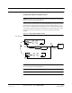

Table Of Contents
- SECTION 1 General Information
- SECTION 2 InterReach Fusion System Description
- SECTION 3 Fusion Main Hub
- SECTION 4 Fusion Expansion Hub
- SECTION 5 Remote Access Unit
- SECTION 6 Designing a Fusion Solution
- 6.1 Overview
- 6.2 Downlink RSSI Design Goal
- 6.3 Maximum Output Power per Carrier
- 6.3.2 700 MHz (Upper C)
- 6.4 System Gain
- 6.5 Estimating RF Coverage
- 6.6 Link Budget Analysis
- 6.6.1 Elements of a Link Budget for Narrowband Standards
- 6.7 Optical Power Budget
- 6.8 Connecting a Main Hub to a Base Station
- 6.8.1 Uplink Attenuation
- 6.8.2 RAU Attenuation and ALC
- SECTION 7 Installing Fusion
- 7.1 Installation Requirements
- 7.1.2 Cable and Connector Requirements
- 7.1.3 Distance Requirements
- 7.2 Safety Precautions
- 7.2.1 Installation Guidelines
- 7.2.2 General Safety Precautions
- 7.2.3 Fiber Port Safety Precautions
- 7.3 Preparing for System Installation
- 7.3.1 Pre-Installation Inspection
- 7.3.2 Installation Checklist
- 7.3.3 Tools and Materials Required
- 7.3.4 Optional Accessories
- 7.4 Fusion Installation Procedures
- 7.4.1 Installing a Fusion Main Hub
- 7.4.3 Installing RAUs
- 7.4.4 Configuring the System
- 7.5 Splicing Fiber Optic Cable
- 7.6 Interfacing the Fusion Main Hub to an RF Source
- 7.6.1 Connecting a Single Fusion Main Hub to an RF Source
- 7.7 Connecting Contact Alarms to a Fusion System
- 7.8 Alarm Monitoring Connectivity Options
- 7.8.1 Direct Connection
- 7.8.5 Ethernet RF Modem
- SECTION 8 Replacing Fusion Components
- SECTION 9 Maintenance, Troubleshooting, and Technical Assistance
- APPENDIX A Cables and Connectors
- APPENDIX B Compliance
- APPENDIX C Faults, Warnings, Status Tables for Fusion, Fusion Wideband, Fusion SingleStar

Help Hot Line (U.S. only): 1-800-530-9960 7-49
D-620610-0-20 Rev F CONFIDENTIAL
Interfacing the Fusion Main Hub to an RF Source
Connecting a Fusion Main Hub to a Roof-top Antenna
TE recommends that you use a lightning arrestor or surge protector in a roof-top
antenna configuration. Insert the lightning arrestor or surge protector between the
roof-top antenna and the repeater connected to the Fusion Main Hub RF Band.
1. Connect an N-male to N-male coaxial cable to the roof-top antenna.
2. Connect the other end of the N-male to N-male coaxial cable to the grounded
surge suppressor.
3. Connect an N-male to N-male coaxial cable to the grounded surge suppressor.
4. Connect the other end of the N-male to N-male coaxial cable to the repeater.
5. Connect an N-male to N-male coaxial cable to the repeater.
6. Connect the other end of the N-male to N-male coaxial cable to the circulator
1 connector.
7. Connect an N-male to N-male coaxial cable to the circulator 2 connector.
8. Connect the other end of the N-male to N-male coaxial cable to the DOWNLINK
connector on the Hub for either Band 1, Band 2, or Band 3.
Attenuation may be required to achieve the desired RF output at the RAU.
9. Connect an N-male to N-male coaxial cable to the circulator 3 connector.
10. Connect the other end of the N-male to N-male coaxial cable to the UPLINK con-
nector on the Hub for either Band 1, Band 2, or Band 3.
Figure 7-29 Connecting a Fusion Main Hub to a Roof-top Antenna
Roof-top
Antenna
Grounded
Surge Suppressor
Repeater
N-male to N-male
Coaxial Cables
N-male to N-male
Coaxial Cable
N-male to N-male
Coaxial Cable
Circulator
Attenuator
(optional)
Note: This applies to either Band 1, Band 2, or Band 3.
Band 1
Band 2
Band 3
UL1 UL2
UL3
DL1
DL2
DL3
AC Power
Alarms
1
2
3