
User's Manual
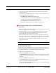


Table Of Contents
- SECTION 1 General Information
- SECTION 2 InterReach Fusion System Description
- SECTION 3 Fusion Main Hub
- SECTION 4 Fusion Expansion Hub
- SECTION 5 Remote Access Unit
- SECTION 6 Designing a Fusion Solution
- 6.1 Overview
- 6.2 Downlink RSSI Design Goal
- 6.3 Maximum Output Power per Carrier
- 6.3.2 700 MHz (Upper C)
- 6.4 System Gain
- 6.5 Estimating RF Coverage
- 6.6 Link Budget Analysis
- 6.6.1 Elements of a Link Budget for Narrowband Standards
- 6.7 Optical Power Budget
- 6.8 Connecting a Main Hub to a Base Station
- 6.8.1 Uplink Attenuation
- 6.8.2 RAU Attenuation and ALC
- SECTION 7 Installing Fusion
- 7.1 Installation Requirements
- 7.1.2 Cable and Connector Requirements
- 7.1.3 Distance Requirements
- 7.2 Safety Precautions
- 7.2.1 Installation Guidelines
- 7.2.2 General Safety Precautions
- 7.2.3 Fiber Port Safety Precautions
- 7.3 Preparing for System Installation
- 7.3.1 Pre-Installation Inspection
- 7.3.2 Installation Checklist
- 7.3.3 Tools and Materials Required
- 7.3.4 Optional Accessories
- 7.4 Fusion Installation Procedures
- 7.4.1 Installing a Fusion Main Hub
- 7.4.3 Installing RAUs
- 7.4.4 Configuring the System
- 7.5 Splicing Fiber Optic Cable
- 7.6 Interfacing the Fusion Main Hub to an RF Source
- 7.6.1 Connecting a Single Fusion Main Hub to an RF Source
- 7.7 Connecting Contact Alarms to a Fusion System
- 7.8 Alarm Monitoring Connectivity Options
- 7.8.1 Direct Connection
- 7.8.5 Ethernet RF Modem
- SECTION 8 Replacing Fusion Components
- SECTION 9 Maintenance, Troubleshooting, and Technical Assistance
- APPENDIX A Cables and Connectors
- APPENDIX B Compliance
- APPENDIX C Faults, Warnings, Status Tables for Fusion, Fusion Wideband, Fusion SingleStar

Fusion Installation Procedures
7-36 InterReach Fusion Installation, Operation, and Reference Manual
CONFIDENTIAL D-620610-0-20 Rev F
7.4.3.2 Installing RAUs in a Multiple Operator System
When installing both iDEN and Cellular systems in parallel, either as dual-band or
multiple operator systems, you must take special provision to assure that the individ-
ual RAUs do not interfere with each other.
The 850/1900 MHz and 800/900/1900 MHz RAU’s antennas must be separated
by at least 8 meters (26 feet) to assure that the iDEN downlink signals do not
interfere with the Cellular uplink signals.
In addition, TE recommends antenna separation when collocating “like” RAUs (for
example, an 850/1900 MHz RAU with an 850/1900 MHz RAU) from different sys-
tems (or layers). This ensures that an antenna disconnect alarm is not triggered by
RAU-to-RAU coupling. The physical spacing between antennas reduces the impact
of adjacent RF sources when performing a System Test. This issue is primarily
related to using closely spaced omni-directional antennas in neutral host installations.
The equation below provides the recommended antenna separation spacing (in
meters):
For a typical application, this translates to about 2 meter antenna spacing at 850 MHz
and about 1 meter antenna spacing at 1900 MHz.
7.4.4 Configuring the System
Before the system can operate properly, use AdminBrowser to program the Fusion
Main Hub with the frequency bands that are to be distributed. The Hub must be pro-
grammed with the same frequencies as the RAU used.
NOTE: The frequency bands should automatically be set on power up and
this step should not be required.
Considerations:
• The AdminBrowser software, described in the AdminBrowser User Manual
(PN D-620607-0-20), must be running on a PC/laptop.
m/s 103 light, of Speed
Hzin Frequency
10dBm input; RAUMax
typ3dBi gain; Antenna
typ16dBm RAU; ofout pwr Comp
10
8
20
4
log202
10
c
Freq
Threshold
AntGain
TxPwr
Spacing
dBm
dBi
dBm
c
Freq
ThresholdAntGainTxPwr
meters
dBmdBidBm