
User Manual


ADCP-75-115 • Issue A • August 2001
Page 7
©
2001,
ADC
Telecommunications,
Inc.
4 LPA USER INTERFACE
The
LPA
user
interface
consists
of
the
various
LEDs,
message
displays,
and
switches
that
are
provided
on
the
LPA
front
panel.
The
LPA
user
interface
points
are
described
in
Table 3
and
indicated
in
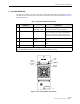
Figure 2.
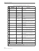
Figure 2. Linear Power Amplifier User Interface
Table 3. Linear Power Amplifier User Interface
REF
NO
USER INTERFACE
DESIGNATION
DEVICE
FUNCTIONAL
DESCRIPTION
1 RESET Momentary
contact
push
button
switch
Momentarily
pressing
the
switch
push
button
clears
all
alarms
and
restarts
the
amplifier
2RF
ON
OFF 2-position
switch Placing
the
switch
in
the
OFF
position
puts
the
LPA
in
a
standby
state
with
RF
output
disabled.
Placing
the
switch
in
the
ON
position
puts
the
LPA
in
the
normal
state
with
RF
output
enabled.
3FAIL LED
indicator
(yellow)
Indicates
the
LPA
is
normal
(off)
or
faulty
(yellow).
4 SHUTDOWN LED
indicator
(red) Indicates
the
LPA
is
in
service
(off)
or
shutdown
(red).
5No
designation Digital
display Provides
status
and
alarm
messages.
See
Note.
Note:
A
more
detailed
description
of
the
digital
display
messages
is
provided
in
the
Digivance
LRCS
Single
Band
SMR
Installation
and
Operation
Manual
(ADCP-75-116)
.
(1) RESET
SWITCH
(2) RF ON/OFF
SWITCH
(3) FAIL
LED
(4) SHUTDOWN
LED
(5) DIGITAL
DISPLAY
16804-A