
User Manual


ADCP-75-114 • Issue 2C • January 2002
Page 2
©
2002,
ADC
Telecommunications,
Inc.
In
the
reverse
path,
the
input
signal
level
received
at
the
DRU
antenna
will
vary
depending
on
the
path
loss
between
the
cell
phone
and
the
antenna
and
the
strength
of
the
cell
phone
signal.
When
the
level
of
the
reverse
path
(uplink)
signal
at
the
DRU
antenna
is
at
a
maximum,
the
composite
maximum
level
of
the
output
signal
from
the
DHU
will
be
–30
dBm.
Therefore,
it
will
generally
be
necessary
to
add
some
gain
to
the
reverse
path
signal
in
order
to
provide
the
output
RF
signal
level
required
at
the
donor
antenna.
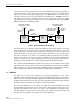
A
block
diagram
showing
a
typical
remote
DHU
to
BTS
interface
is
provided
in
Figure
2.
DIRECTIONAL ANTENNA
TO/FROM CELL SITE BTS
16425-B
REMOTE
INTERFACE
UNIT
FORWARD
(DOWNLINK)
REVERSE
(UPLINK)
-40 dBm
(COMPOSITE
MAX)
-20 dBm
(COMPOSITE MAX)
-30 dBm
(COMPOSITE MAX)
DIGITAL
HOST
UNIT
OPTICAL LINK
OPTICAL LINK
DIGITAL
REMOTE
UNIT
DIRECTIONAL ANTENNA
TO/FROM HANDSETS
+13 dBm FOR 800 MHz
+16 dBm FOR 1900 MHz
(COMPOSITE MAX)
Figure 2. Remote BTS Interface Block Diagram
The
RIU
consists
of
an
electronic
circuit
board
assembly,
power
supply,
duplexer,
and
linear
power
amplifier
that
are
mounted
within
a
powder-coated
sheet
metal
enclosure.
The
metal
enclosure
provides
a
mounting
point
for
the
electronic
components,
serves
as
a
heat
sink,
and
controls
RF
emissions.
Except
for
the
fan,
the
electronic
components
are
not
user
replaceable.
The
RIU
is
designed
for
use
within
a
non-condensing
indoor
environment
such
as
inside
a
wiring
closet
or
cabinet.
All
controls,
connectors,
and
indicators
are
mounted
on
the
RIU
front
panel
for
convenient
access.
Cable
management
functions
for
the
power
and
coaxial
cables
are
provided
by
a
cable
management
tray
that
extends
outward
from
the
RIU
front
panel.
Two
versions
of
the
800
Mhz
RIU
are
available.
One
version
is
used
to
interface
with
an
A-band
BTS
and
the
other
version
is
used
to
interface
with
a
B-band
BTS.
Six
versions
of
the
1900
MHz
RIU
are
available,
one
version
for
each
of
the
six
1900
MHz
sub-bands.
The
appropriate
frequency
and
sub-band
are
clearly
marked
on
a
label
attached
to
the
RIU
cable
management
tray
1.2 Mounting
The
RIU
may
be
used
in
both
rack-mount
and
wall-mount
applications.
For
rack
mount
applications,
a
pair
of
reversible
mounting
brackets
is
provided
that
allow
the
RIU
to
be
mounted
in
either
a
19-inch
or
23-inch
EIA
or
WECO
equipment
rack.
When
rack-mounted,
the
front
panel
of
the
RIU
is
flush
with
the
front
of
the
rack.
The
cable
management
tray
extends
3.9
inches
(99
mm)
beyond
the
front
panel.
Fasteners
are
provided
for
rack-mount
applications.
For
wall-mount
applications,
a
pair
of
holes
is
provided
in
the
cable
management
tray
which
allow
the
RIU
to
be
mounted
on
any
flat
vertical
surface.
The
mounting
brackets
may
also
be
removed
and
reinstalled
is
such
a
way
as
to
be
used
to
secure
the
RIU
to
a
flat
vertical
surface.
The
RIU
should
be
oriented
with
the
front
panel
facing
upward
when
wall-mounted.
The
fasteners
must
be
provided
by
the
installer
in
wall-mount
applications.