
User Manual


ADCP-75-150 • Preliminary Issue A • March 2003 • Section 2: Description
Page 2-21
©
2003,
ADC
Telecommunications,
Inc.
6.5 Cooling
Continuous
air-flow
for
cooling
is
provided
by
a
fan
mounted
at
the
front
of
the
LPA
housing.
Cool
air
is
pulled
into
the
module
from
the
front
and
heated
air
is
exhausted
out
the
back.
An
alarm
is
provided
that
indicates
if
a
high
temperature
condition
(>50º
C/122º
F)
occurs
or
if
a
fan
failure
occurs.
The
fan
may
be
field
replaced
if
it
fails.
6.6 User Interface
The
LPA
user
interface
consists
of
an
LED
indicator
and
a
switch
that
are
mounted
on
the
LPA
front
panel.
The
LPA
user
interface
points
are
described
in
Table 2-5
and
indicated
in
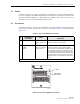
Figure 2-10.
Figure 2-10. Linear Power Amplifier User Interface
Table 2-5. Linear Power Amplifier User Interface
REF
NO
USER INTERFACE
DESIGNATION
DEVICE
FUNCTIONAL
DESCRIPTION
1 STATUS LED
indicator
(green,
yellow,
and
red)
Indicates
the
operational
state
of
the
LPA
and
whether
or
not
there
are
any
faults.
2MUTE
NORM
RESET
3-position
switch
with
one
momentary
contact
position
Placing
the
switch
in
the
MUTE
position
puts
the
LPA
in
the
shutdown
state
with
RF
output
dis-
abled.
With
the
switch
in
MUTE,
the
STM
can
not
control
the
LPA
output
power.
Placing
the
switch
in
the
NORM
position
puts
the
LPA
in
the
normal
state
and
allows
the
STM
to
enable
and
disable
the
RF
output.
Momentarily
placing
the
switch
in
the
RESET
position
clears
all
alarms
and
restarts
the
LPA.
Note:
A
more
detailed
description
of
the
STATUS
LED
is
provided
in
Section
5.
18639-A
STATUS
MUTE
NORM
RESET
(1) STATUS
(2) MUTE/NORM
/
RESET SWITCH