In-Building Wireless Solution User Manual Software Version 5.
Uniwave User Manual © 2016-2022 Zinwave Ltd All Rights Reserved Zinwave retains all ownership rights to all computer programs offered by Zinwave, their products, and the contents of this manual. The source code for both software and firmware are confidential trade secrets of Zinwave. You may not attempt to decipher, decompile, develop or otherwise reverse engineer Zinwave software, firmware, or products. Information necessary to achieve interoperability is furnished upon request.
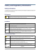
Table of Contents Safety and Regulatory Information................................................... vii Safety Information ............................................................................................................................ vii RF Exposure ...................................................................................................................... vii Installation..............................................................................................................
2.2 2.3 2.4 2.5 2.6 3 2.1.2 Primary Hub ..................................................................................................... 2-2 2.1.3 Secondary Hub ................................................................................................ 2-3 Service Module ......................................................................................................... 2-4 Optical Module .......................................................................................................
6.2 7 Powering Remote Units ............................................................................................ 6-5 6.2.1 PSU DC Power ................................................................................................ 6-5 DAS Installation Considerations ............................................ 7-1 7.1 7.2 7.3 7.4 7.5 Antenna Requirements ............................................................................................. 7-1 7.1.1 Isolation .........................
10.4 10.5 10.6 10.7 10.8 10.9 11 11.1 11.2 11.3 11.4 12 12.1 12.2 12.3 12.4 13 13.1 10.3.6 Secondary Hub Configuration and Controls .................................................. 10-5 10.3.7 Remote Unit Configuration ............................................................................ 10-5 System Status ......................................................................................................... 10-6 10.4.1 System Status Topology Tree and Modules ..............................
13.2 13.3 13.4 14 14.1 14.2 14.3 14.4 14.5 15 13.1.4 Informational ................................................................................................ 13-26 Alarms Setup ......................................................................................................... 13-27 Alarm Connections ................................................................................................ 13-27 SNMP ......................................................................................
Safety and Regulatory Information Safety Information The following safety warnings and cautions are listed to prevent damage to equipment or property and prevent any risk of personal injury. RF Exposure Warning: This equipment complies with European, FCC and Canadian radiation exposure limits set forth for an occupational/ controlled environment.
DOUBLE POLE/NEUTRAL FUSING The Power Supply Module in the Primary Hub 308-0001, and in the Secondary Hub 308-0004 has multiple sources and may include a fuse in the Neutral AC connection. Disconnect the AC mains supply to de-energize the phase conductors. After operation of the fuse, parts of the equipment that remain energized might represent a hazard during servicing.
Optical Safety Precautions Warning: Use of controls or adjustments or performance of procedures other than those specified herein may result in hazardous radiation exposure. Caution: Do not remove the fiber Port dust covers unless the port is in use. Do not stare directly into a fiber Port. Caution: Cover any unconnected fiber ends with an approved cap. Caution: Do not stare with unprotected eyes at any broken ends of the fiber. Caution: Use only approved methods for cleaning optical fiber connectors.
Symbols This section identifies the symbols that are displayed on Uniwave devices. Labels or symbols may not appear on every device. Symbol Description Consult Manual Electric shock hazard UL certified UL NRTL Listing The European CE mark The UKCA (UK Conformity Assessed) marking is a new UK product marking that is used for goods being placed on the market in Great Britain (England, Wales and Scotland). It covers most goods which previously required the CE marking.
• RoHS DIRECTIVE 2011/65/EU • UL2043 compliance In reference to UL2043 compliance, Remote Units are suitable for use in environmental air space in accordance with Section 300-22(c) of the National Electrical Code, and Sections 2-128, 12-010(3) and 12-100 of the Canadian Electrical Code, Part 1, CSA C22.1. Note: The system contains a device which is classified as a “CLASS I LASER PRODUCT”, with an internal Class 1 laser source (as defined in CBTR # DE3-500286 by TUV).
When operating on a channel or channels under 47CFR parts 24 or as identified in the following table, the 308-0007-1 and 308-0007-2 Remote Units are an Industrial Booster as per 47CFR part 20.
Uniwave Installation & Configuration Manual About this Manual About this Manual This manual provides user instructions for the Uniwave In-Building Wireless Solution. Intended Audience The intended users for this manual are trained and competent in the configuration of Distributed Antenna Systems (DAS). Conventions Icons are used to alert you to potential safety hazards in one of the following ways: Warning: A warning notice denotes a hazard.
Uniwave User Manual System Overview 1 System Overview Zinwave’s Uniwave in-building wireless solution provides cellular and public safety access services to buildings, campuses, and venues, delivering end-to-end all fiber service on a single converged system. Zinwave’s unique wideband architecture supports any service mix, protocol, or modulation scheme over a wide frequency range. The 308-XXXX product components cover 150 MHz to 6000 MHz (NB 308-0007-x currently support 150 – 5000 MHz).
Uniwave User Manual System Overview 1.2 Key Features The Uniwave solution provides the following key features: • Wideband 150 – 6000MHz capability • Supports single star or double star topologies, supporting up to 64 Remote Units. • Single mode Fiber (SMF) from head-end to antenna • Supports Frequency Division Duplex (FDD) and Time Division Duplex (TDD) • Modular Primary and dedicated Secondary Hubs, with 48V PSU functionality for powering Remote Units incorporated in Secondary Hub.
Uniwave User Manual System Overview 1.3.2 Double Star Configuration In its double star configuration, Uniwave supports a single Primary Hub connected to up to 8 Secondary Hubs each supporting 8 Remote Units, bringing the system total to up to 64 Remote Units. 1.3.
Uniwave User Manual System Overview 1.3.4 Support for MIMO Services The next generation of high data-rate services such as LTE provide various multiple-input and multipleoutput (MIMO) options. Where base stations (BTS) are deployed to provide in-building coverage, these options can be used to increase the overall capacity or coverage of the system.
Uniwave User Manual System Overview for MIMO A and 64 for MIMO B. This is because each location now has 2 Remote Units with 2 Tx and 2 Rx antennas. The number of antenna locations is now 64. If MIMO antennas (which have 2 RF connections) are used, the number of antennas is 32 for MIMO Tx and 32 for MIMO Rx. The number of antenna locations is now 32. Note: The MIMO routing is done via the Signal Routing Matrix in the Primary Hub. 1.
Uniwave User Manual System Overview 1.4.2 How the Active POI Fits in The Active POI provides the interconnection between the RF source (for example, high power sources like BTS or repeaters where significant attenuation is needed) and the Service Module that is installed in the Primary Hub. Its compact design provides multiple passive elements for signal conditioning/ attenuation.
Uniwave User Manual Understanding the Components 2 Understanding the Components Uniwave has core and optional components. Core components are all necessary for system operation.
Uniwave User Manual Understanding the Components installed on. Detailed functionality of the GUI is provided in the later sections of this manual. 2.1.2 Primary Hub A Primary Hub provides the interface to the RF sources and converts RF signals to optical. It then connects via fiber to either Secondary Hubs and/or Remote Units. The Primary Hub includes at least one Service Module (see “Service Module”). Service Modules interface with RF sources such as base stations or repeaters.
Uniwave User Manual Understanding the Components Front View 1 2 3 4 7 8 Number Description 1 Slots1 to 8 for Optical Modules or Transport Modules 2 Ethernet connector 3 USB Connector (Type A) 4 USB Connector (Type A) 5 RS232 Connector 6 Alarm Connector (9 way D-type) 7 Status LEDs 8 Handle and Mounting Bracket (both sides of device) Copyright © 2022 Zinwave. All rights reserved.
Uniwave User Manual Understanding the Components Rear View Number Description 1 Slots A to D (right to left, from the rear view) for Service Modules or Transport Modules. 2 Optional Grounding Post, main protection is provided in the IEC inlet. 3 IEC AC Power Cord Connector shown. 4 Fuse 5 On/Off Power Switch 2.1.3 Secondary Hub A Secondary Hub receives input via an optical link from a Primary Hub to distribute RF feeds between the Primary Hub and Remote Units.
Uniwave User Manual Understanding the Components Front View 1 2 3 4 5 Number Description 1 Duplex SC-APC/SC-APC Optical connection to the Primary Hub 2 Duplex SC-APC/SC-APC Optical connection to a Remote Unit (8 positions) 3 Phoenix Contact 5.08mm connector: 48V power for a Remote Unit (8 positions) 4 Alarm Connector (9 way D-type) 5 IEC AC Power Cord Connector 2.2 Service Module Service Modules provide the interface to the RF signal source such as BTS, or small cell.
Uniwave User Manual Understanding the Components Rear View 1 2 3 Number Description 1 Floating BMA RF Connector 2 Floating BMA RF Connector 3 Multi-pin Data and Power Connector 2.3 Optical Module The Optical Module provides the fiber link between a Primary Hub and a Secondary Hub or a Remote Unit. Up to 8 Optical Modules can be installed in the front of a Primary Hub to connect to Remote Units or Secondary Hubs as required.
Uniwave User Manual Understanding the Components Rear View Number Description 1 Floating BMA RF Connector 2 Floating BMA RF Connector 3 Multi pin Data and Power Connector 2.4 Transport Module The Transport Module provides the fiber link between two cascaded Primary Hubs. The Transport Module is visually similar to an Optical Module, but with internal hardware differences to permit it to also perform the job of a Service Module. It is not interchangeable with an Optical Module.
Uniwave User Manual Understanding the Components Rear View Number Description 1 Floating BMA RF Connector 2 Floating BMA RF Connector 3 Multi pin Data and Power Connector 2.5 Remote Unit The Remote Unit is a small, wall or ceiling mountable unit that amplifies the downlink signals for transmission over a wireless link, and amplifies the uplink wireless signals for transmission over the optical link. It is connected to the Primary or Secondary Hub via optical fiber.
Uniwave User Manual Understanding the Components Top View 1 2 Number Description 1 Antenna Connector Transmit (Tx) Coax N type 2 Antenna Connector Receive (Rx) Coax N type 2.5.1 Antennas A variety of antennas can be connected to the Remote Unit via short coaxial cables. The choice of antenna will depend on the service requirement within the operational bandwidth of the system. Up to 8dBi antenna gain is permitted according to the regulatory approvals for the system.
Uniwave User Manual Understanding the Components mode UPC fiber connector, and Green for Single mode SC-APC (angled polished) connectors. The UniWave 308-0007 Remote Unit is equipped with more modern duplex LC-APC fiber connectors. The fibers are the same type and orientated the same way as with all of the other Zinwave components, but the connector body is smaller. Copyright © 2022 Zinwave. All rights reserved.
Uniwave User Manual Hub and Module LEDs 3 Hub and Module LEDs 3.1 Primary Hub Front Panel LEDs There are four LEDs on the front of the Primary Hub. The following table describes them: Symbol Name Status Color Description Comment Power Indicator Green Power connected to CPU board Shows processor is correctly powered Off No power connected Green No error.
Uniwave User Manual Hub and Module LEDs 3.2.2 Optical Links to 8x Remote Units LED Color Description Off No Remote Unit laser detected on port, and no Remote configured to be present on port. Red Remote unit configured to be present on port, but no Remote Unit laser detected Red Flash Alarm active on Remote Unit attached to port Alternate Red/ Green Waiting for attached Remote Unit to be associated with Primary Hub (once Remote Unit laser detected).
Uniwave User Manual Hub and Module LEDs through the installed modules. During this period, the Primary Hub checks for the presence of any Secondary Hubs and Remote Units. For Optical Modules, if no Remote Units are connected, only the right and middle LEDs are operational. Initially the right LED will be a dull red, indicating that power is connected but the module is disabled. This will change to green when the Hub has detected the presence of the module and initialized it.
Uniwave User Manual Hub and Module LEDs 3.3.3 Status—Left LED Color Service Module Optical / Transport Module Off Normal condition Module is not powered, or optical calibration and autosetup of downstream units not yet completed. Green Not Used Optical / Transport Module and all downstream system elements operating normally.
Uniwave User Manual Left Hub and Module LEDs Middle Right Status Optical Module inserted in invalid slot. (E.g. In an input (rear) slot). Off Off Green Optical Module successfully detected, starting discovery of downstream system elements. Off Red Green Potential communication failure state: No incoming light on fiber or no downstream system elements have responded after several communication attempts (discovery continues).
Uniwave User Manual Left Middle Right Status Off Off Dull Red Initial power-up. Power present on Hub allowing Transport Module to be detected; or Transport Module NOT Enabled through System Setup. Off Off Green Transport Module successfully detected, starting discovery of downstream Primary Hub. Off Red Green Potential communication failure state: No incoming light on fiber or no messages from upstream UniTransport Hub.
Uniwave User Manual Performing a Basic Installation 4 Performing a Basic Installation The following procedure is intended to provide you with a basic work flow to get a new system up and running. It provides references to specific instruction for that step. To install Uniwave: 1) Unpack and verify all components (See section “Installing and Populating Hubs” ). 2) Rack mount Hubs and populate with the appropriate modules (See section “Installing and Populating Hubs”).
Uniwave User Manual Installing and Populating Hubs 5 Installing and Populating Hubs This chapter describes how to install insert modules into Primary and Secondary Hubs. 5.1 Installing the Hub You can mount a Primary or Secondary Hub in a standard 19" (48.26cm) rack or an open frame rack. There are many 19" rack systems available on the market of various depths. It is essential that the weight of the Hub is supported at the front and back.
Uniwave User Manual Installing and Populating Hubs 5.1.2 Standard 19" (48.26cm) Rack Mounting The Primary Hub is deigned to mount directly into a 19 inch rack framework with no additional mounting materials. The following tools are required for installation (Not provided): • 4x M6 cage nuts appropriate for 19 inch rack frame • Pozi-drive screwdriver • Cage nut insertion/extraction tool Note: If rack frame does not use M6 nuts, you must supply appropriate nuts to secure the Hub.
Uniwave User Manual Installing and Populating Hubs To install the Primary Hub in a rack: 16) Remove all parts from the Accessory Box included in the box with the Hub. 17) Attach the mounting brackets (using the black countersunk screws 128-0118) to the side of the Hub in the correct position for the rack. 18) Place the Primary Hub into the rack and secure using suitable Hub mounting screws and washers. 5.1.4 Installing Blank Panels Blank panels are available to cover unused slots on a Primary Hub.
Uniwave User Manual Installing and Populating Hubs 5.2 Installing Secondary Hub The Secondary Hub is designed to mount directly into a 19-inch rack framework with no additional mounting materials. Below dimensions are in millimeters. Copyright © 2022 Zinwave. All rights reserved.
Uniwave User Manual Copyright © 2022 Zinwave. All rights reserved.
Uniwave User Manual Installing and Populating Hubs 5.3 Installing Service Modules in Primary Hub Service Modules are inserted in the back of a Primary Hub in slots A to D. See “Primary Hub” for slot descriptions. Caution: Service Modules must ONLY be installed in the REAR of a Primary Hub. Optical Modules must ONLY be installed on the front panel of a Primary Hub or the unit will not function as expected.
Uniwave User Manual Installing and Populating Hubs 5.4 Installing Optical Modules in Primary Hub Optical Modules are inserted in the front of Primary Hubs. To install Optical Modules Note: If you are adding or updating modules, remove any blanking plates in the slots you wish to populate by turning the retaining screw and pulling on the top and bottom of the plate. 1.
Uniwave User Manual Installing and Populating Hubs Note: If powered up with no modules installed the Primary Hub shows 4 green LEDs. If modules are installed then the alarm warning and fault LEDs may show alarm conditions at initial start-up. This could be due to the fact that no Remote Unit elements are connected. These alarms can be cleared via the Primary Hub Set Up page of the Configuration GUI once the system is correctly configured.
Uniwave User Manual Installing Remote Units 6 Installing Remote Units This chapter describes how to install the Remote Units along with their power options. 6.1 Mounting Remote Units Your system installation plan provides the locations to mount each Remote Unit and their associated antennas. Depending on the available wall space a Remote Unit can be mounted vertically (with antenna connector closest to ceiling) or horizontally (with antenna connectors facing a side wall).
Uniwave User Manual Installing Remote Units 89.70 224.00 231.00 270.00 286.60 89.70 72.00 308-0007-1 Uniwave Remote Unit Copyright © 2022 Zinwave. All rights reserved.
Uniwave User Manual Installing Remote Units 89.70 443.00 450.00 270.00 286.60 89.70 72.00 308-0007-2 Uniwave 2-Path Remote Unit • Ensure that adequate space is provided to allow for any power and signal cables to be connected and that minimum bend radii of cables are met. • Make sure there is room for antenna connections to exit through the ceiling. • Make sure there is adequate clearance around the Remote Unit to allow some convection. Copyright © 2022 Zinwave. All rights reserved.
Uniwave User Manual Installing Remote Units The following wall bracket is provided for mounting a Remote Unit: 224.00 150.00 75.00 75.00 20.00 75.00 210.00 75.00 20.00 Ø6 .50 Wall Bracket for 308-0007-1 Uniwave Remote Unit 443.00 370.00 75.00 .50 75.00 20.00 75.00 210.00 75.00 20.00 Ø6 Wall Bracket for 308-0007-2 Uniwave 2-Path Remote Unit 1. Place the mounting bracket on the wall in the desired location and position (Horizontal or Vertical). 2.
Uniwave User Manual Installing Remote Units 4. 5. 6. 7. Drill the 6 screw holes. Attach the bracket to the wall using a screwdriver and suitable screws. You may need to use additional hardware such as rawlplugs, for a secure fit. Align the lugs on the side of the Remote Unit with the dog-leg slots in the bracket. Orientate the product such that the cooling fins provide the best convection. This may mean that the fins are outermost or uppermost. 8.
Uniwave User Manual Installing Remote Units To connect the PSU to the Remote Unit. 1. 2. 3. 4. Connect/plug the cable to the appropriate connector on the PSU or Secondary Hub. Route the cable from the PSU / Secondary Hub to the Remote Unit. Plug the cable into the 48V connector on the Remote Unit. Repeat for each PSU / Secondary Hub to Remote Unit connection. Once power is plugged in, the unit is powered on. Note: It is recommended to connect fiber prior to powering on the Remote Unit.
Uniwave User Manual DAS Installation Considerations 7 DAS Installation Considerations This chapter describes requirements and considerations to get the best performance from your DAS. 7.1 Antenna Requirements This section describes antennas that can be connected to Remote Units. For physical connection of the antenna to the Remote Units see “Connecting Antennas to Remote Units”. 7.1.
Uniwave User Manual 7.2 Uplink/Downlink Balance Care should be taken not to separate the two antennas by so much distance that the path difference between Tx and Rx to the mobile affects system performance. Some services are more affected by uplink/downlink path difference than others, especially those using high dynamic range mobile powercontrol such as WCDMA.
Uniwave User Manual 7.4 Connecting the PSU or Secondary Hub Power Port to Remote Units 7.4.1 Power Distribution Requirements Power for Remote Units is generally supplied from a centrally located source – either a dedicated PSU or a Secondary Hub - that drives multiple Remote Units. The distance of the Remote from the centralized location depends upon the cable type used.
Uniwave User Manual Wire Conversion Chart: American Wire Gauge to Square Millimeters AWG mm2 AWG mm2 AWG mm2 AWG mm2 30 0.05 18 0.75 6 16 4/0 120 28 0.08 17 1.0 4 25 300 MCM 150 26 0.14 16 1.5 2 35 350 MCM 185 24 0.25 14 2.5 1 50 500 MCM 240 22 0.34 12 4.0 1/0 55 600 MCM 300 21 0.38 10 6.0 2/0 70 750 MCM 400 20 0.50 8 10 3/0 95 1000 MCM 500 7.4.2 Understanding Connectors & Cabling Cabling between the PSU or Secondary Hub is not supplied.
Uniwave User Manual 7.5 Uplink System Noise 7.5.1 Introduction Anything with active electronics will generate some level of noise in addition to the desired function. Usually this becomes a consideration in an amplifier system such as an Active DAS. Cellular systems assess “noise” as part of their operation and its presence is monitored and can cause an alarm condition. Older 2G (GSM) technology usually has an alarm for “interference” which an excessive noise level will trigger.
Uniwave User Manual Calculated using Empirical Formula: NF= 14 + 10 x LOG (SQRT(qty of RUs)) + 10 x LOG (SQRT(qty of SHs)) Data Table of ORU/SH com binations number of ORU/SH ---> Noise Figure number of SH ---> 1 2 3 4 5 6 7 8 1 14.0 15.5 16.4 17.0 17.5 17.9 18.2 18.5 2 17.0 18.5 19.4 20.0 20.5 20.9 21.2 21.5 3 18.8 20.3 21.2 21.8 22.3 22.7 23.0 23.3 4 20.0 21.5 22.4 23.0 23.5 23.9 24.2 24.5 5 21.0 22.5 23.4 24.0 24.5 24.9 25.2 25.5 6 21.8 23.3 24.
Uniwave User Manual 7.5.3 UniTransport Cascading two Primary Hubs in a UniTransport system makes little difference to the foregoing discussion. The overall gain between a Service Module in the UniTransport Hub and a Remote Unit in the downstream Primary Hub is configured to have the same gain as if the Service Module had been plugged directly into the downstream Primary Hub.
Uniwave User Manual Performing Basic Configuration 8 Performing Basic Configuration The following procedures are intended to be executed after the hardware installation is complete. All hardware has been installed and configured with at least an IP address. All equipment is connected, and the system is ready to be configured To Configure Uniwave : 1. The Zinwave Coverage Tool is used to plan the system and calculate the setting required for its deployment.
Uniwave User Manual Understanding the Configuration GUI 9 Understanding the Configuration GUI A Configuration Graphical User Interface (GUI) is available to configure your equipment locally or remotely via ethernet. The GUI is hosted on the Primary Hub and is used to configure and monitor the Primary Hub and all connected Secondary Hubs and Remote Units. This section describes how to access the GUI and the general features of this interface.
Uniwave User Manual Understanding the Configuration GUI To change the IP address of the standalone PC: 1. Set the standalone PC to use a static IP address on the same subnet e.g. 192.168.0.3, with a subnet mask of 255.255.255.0. 2. Make an Ethernet connection from the standalone PC to the Primary Hub (either a crossover or straight-through Ethernet cable can be used). 3. Access the GUI as described in “Accessing the GUI” and go to the Hub Setup page to change the IP address. See “IP Settings”.
Uniwave User Manual Understanding the Configuration GUI 9.3 Accessing the GUI The GUI is initially accessible via a Web browser through a secure (https) connection (but can be changed to an unsecured (http) connection via the “User Interface Settings” section of the Hub Setup page.) For initial configuration of a device, you need local access via an ethernet connection to the front of the Primary Hub.
Uniwave User Manual Understanding the Configuration GUI Username Default Password Description viewer No Password View system status but cannot make any changes. basic installer View system status and can make only a subset of configuration changes. advanced supervisor View and change all options. See “Changing User Passwords and Timeouts” for information on changing passwords. 9. Click Log In. 10. On successful login, the System Status window appears.
Uniwave User Manual Understanding the Configuration GUI 9.4 Understanding the Main Window Once logged in, the Main Window is displayed. Depending on the browser used, the look and feel may differ slightly, but the functionality remains the same. The GUI opens to the System Status page by default and displays the Hub to which the PC is connected. 9.4.1 Address Bar The address bar displays the IP address of the Hub you are currently logged into.
Uniwave User Manual Understanding the Configuration GUI To access help: 1. Click the arrow Help button on the right side of the screen. The help window opens with help specific to your current screen. 2. View the help and click through to get to additional information, if desired. 9.4.4 Display Area The Display area shows the screen selected via the top-left navigation bar.
Uniwave User Manual Understanding the Configuration GUI 9.4.6 Changing User Passwords and Timeouts In the Security Settings section of the Hub Setup page an “advanced” user can change the password for both an “advanced” and “basic” user. The Inactivity Timeout period can be set too. To change User Security settings for a Hub 1. Click Hub Setup in the left navigation bar. The Current user is shown in the Security Settings pane. 2.
Uniwave User Manual Understanding the Configuration GUI Advanced users can also choose to “keep me Logged in”. 3. To change a user password… 1. 2. 3. 4. Select the user type password to change from the pulldown. Enter a new password Re-enter the new password. Click Update. Copyright © 2022 Zinwave. All rights reserved.
Uniwave User Manual Initial System Setup 10 Initial System Setup This chapter provides the basic configuration setup items to get a system up and running. Note: If you wish to setup SNMP during the initial setup of the system, see “SNMP”. 10.1 Connection to DAS System The entire DAS system is setup and configured via the Configuration GUI on the Primary Hub. Access the GUI on your Primary Hub using a Web Browser, as described in the previous section. 10.
Uniwave User Manual Initial System Setup To install a new software release: The software release ‘.dat’ file must be accessible to the system hosting the Web browser being used to access the Configuration GUI. Go to the Software Upgrade page. Select New Software Release Click the 'Choose File…' button to select a full new Software Release to be uploaded to the system. The software version details will be displayed.
Uniwave User Manual Initial System Setup Note that the entire DAS will be rebooted when a full new software Installation takes place. Please wait for all the RUs and SHs to be Flashed, after which the Primary Hub will reboot. Following the system restart, warnings will be displayed if any SHs or RUs contain firmware that is not the expected version. If any unexpected firmware versions are reported, use the option to ‘Update RU and SH Firmware from Installed Hub Software’. 10.2.
Uniwave User Manual Initial System Setup Calculated Input Level (dBm) corresponds to the RF level on the fiber, which is recommended to be set to -25dBm. Separately, the relative mix of power levels from each service input is specified by the Calculated Relative Power Level. The dominant input is set to 0dB, and the lesser inputs are set to a negative dB value. This determines the mix of signal levels appearing at the Remote Unit outputs.
Uniwave User Manual Initial System Setup to a Downstream Primary Hub. The System Setup screen shows a table entitled Downstream PH Configuration, where the UL AGC Threshold is configured. Similar to the settings for a Remote Unit, the level is in absolute power (dBm). Typically this is set to -20dBm. Signal limiting will occur until the available attenuation in the Transport Module is exhausted (31dB range). 10.3.
Uniwave User Manual Initial System Setup a 0.5dB hysteresis margin). The Uplink AGC operating region continues through higher uplink signal levels, until the AGC/overload attenuator in the Remote Unit has run out of range. This is typically 5 to 20 dB of active AGC range. At that point the uplink will be switched off to protect the system.
Uniwave User Manual Initial System Setup o • • • Service Module (SM) - Provides interface for RF services from BTS, etc. The table also shows input Transport Modules (TMs) o Optical Module (OM) - Provides optical links to a Secondary Hub or Remote Unit. The table also shows any output Transport Modules (TMs). Secondary Hub (SH): Fans out optical links from the PH to up to 8 Remote Units per SH. Remote Unit (RU): Provides RF connections to antennas for Tx/Rx to RF devices.
Uniwave User Manual Initial System Setup have such a device set this field to 0.0.0.0. 10.6.3 SNMP Settings Trap IP Address The network address to which traps are to be sent. This would usually be the network management computer. Setting this field to 0.0.0.0 disables traps. Trap Port The UDP port number to which traps are sent. For most systems this will be 162. Trap Type SNMP traps can be configured to use either the “Trap” or “Inform” transport mechanism.
Uniwave User Manual Initial System Setup This is the IP address of the NTP server used to synchronize the time. Time Zone Select your Time Zone from the pre-defined drop-down list. Ignore the "Custom TZ String" field if your Time Zone is available. If your Time Zone is not available please contact Zinwave, who will provide a custom TZ string. Note: Any change to the Date & Time configuration will result in the Hub restarting.
Uniwave User Manual Initial System Setup interrupted. In this section, the user can set the start time for the system maintenance window. Only one action will occur at a time in the order (when more than one is scheduled): Software Installation, RF Calibration then System Check. The user can also check the status of any scheduled actions.
Uniwave User Manual Initial System Setup 10.9 System Views The System Views section provides collated Status/Configuration Information related to the DAS. 10.9.1 System Snapshot This section provides the view of the entire system configuration and status information for the DAS in a tabular form. The user can save the view as an HTML file that can be displayed by any supported browser. 10.9.
Uniwave User Manual Initial System Setup PA Health is highlighted amber when there is 8dB or greater difference between the Tx output power and the expected level from measuring the input power and red if there is no measurable output power. A fault may actually be due to mismatch at the Tx port of the RU, rather than the PA. If the background RF pickup is > -30dBm when the DAS is off it shows amber; if it is > -20dBm it shows red.
Uniwave User Manual Additional System Setup 11 Additional System Setup 11.1 System Uplink/Downlink Balance The uplink / downlink balance allows for variation in transmit and receive path gains depending upon system requirements. A mobile device will estimate the level at which it should register with the basestation, based on its received downlink strength, and adjusting the balance in the DAS affects the reliability of devices registering on the system.
Uniwave User Manual Additional System Setup units are missing. Apply a new system setup to acknowledge them”. This is because the system has changed from the baseline configuration set up after the Apply button was pressed. Do not make any equipment changes while the system is validating its set up as this will invalidate any System Setup process and the setup will fail. A message will be displayed indicating the failure and request that you run System Setup again. 11.3.
Uniwave User Manual Additional System Setup 2. You need to insert the tip of the device into the hole as the button is set in from the front face. The Hub restarts and the LEDs flash. The Hub is returned to the default IP address and configuration settings: • IP Address: default 192.168.0.2 • Sub Net: Default 255.255.255.0 • Gateway: Default 192.168.0.
Uniwave User Manual UniTransport System Setup 12 UniTransport System Setup 12.1 UniTransport Functionality The UniTransport concept permits any primary hub to accept service connections over fiber, in place of coax. Remotely situated base-stations can be connected to a UniTransport hub which is populated with Service Modules in the rear slots and Transport Modules in the front slots. Identical Transport Modules are configured in the Service slots of each Primary Hub to receive those services.
Uniwave User Manual UniTransport System Setup The Transport Module is visually similar to an Optical Module, but with internal hardware differences to permit it to also perform the job of a Service Module. It is not interchangeable with an Optical Module. A pair of Transport Modules is required to create a UniTransport link.
Uniwave User Manual UniTransport System Setup Zinwave recommends that the DL IP power presented to the Downstream PH is set to -25dBm. Also set the UL AGC Threshold to a little higher than this, -20dBm is recommended. The settings are calculated when you click Validate Settings, and applied to the hardware when you then click the Apply Settings button.
Uniwave User Manual UniTransport System Setup 12.4 Remote Configuration of UniTransport Hub The physical separation of the UniTransport hub could be several kilometres from the Primary Hubs it serves. To assist with configuring the services arriving at a downstream Primary Hub, there is a Setup button associated with each input Transport Module on the System Setup page of the GUI.
Uniwave User Manual UniTransport System Setup The Services provided by the UniTransport hub may also be routed to its own Secondary Hubs and Remote Units as well as other hubs, so keep in mind that changing any power levels and switch settings will have a wider effect. Copyright © 2022 Zinwave. All rights reserved.
Uniwave User Manual Understanding Alarms & Reporting 13 Understanding Alarms & Reporting 13.1 Alarms The term Event is a generic term for any occurrence in the system that could cause an entry in the Event Log to be generated. Events are defined into four categories. • Loss of Service • Service warning • Hardware Warning • Informational Some events also cause alarms and are sub-divided as described in the following sections.
Uniwave User Manual Understanding Alarms & Reporting Alarm Description Action The uplink power has exceeded the safe limit, and the receiver has been turned off The power in the uplink (primarily the Remote Unit) has exceeded the defined threshold. This will cause the LNA in the Remote Unit to switch off until the overload condition is removed. It can be caused by uncontrolled uplink power from mobiles or by poor installation causing reduction in Tx Rx isolation.
Uniwave User Manual Alarm Understanding Alarms & Reporting Description Action This indicates that the Remote Unit has detected a signal that has reach the “UL AGC Threshold”. It is currently working in a “limited” region before it switches off completely. This indicates that the Remote Unit is sensing a higher than expected uplink RF level.
Uniwave User Manual Understanding Alarms & Reporting Alarm Description UL gain setting too high, decrease balance “Required uplink gain is too high.” Input level too low changing to appropriate level “The SM Calculated Input Level has been changed to prevent the downlink gain from being too high.” Different power levels on uplink matrix input 13.1.3 The uplink gain is potentially greater than the downlink gain. The system cannot achieve the required output with the input level set on the Set-Up page.
Uniwave User Manual Understanding Alarms & Reporting Alarm Description Current1 under limit This indicates a problem with the power supply rails of the device in question. In the case of Optical Modules, Service Modules and Hub alarms it relates to the Hub Power supply. If the alarm is raised in conjunction with a Remote Unit, the fault will be with local unit or the centralized feed.
Uniwave User Manual Understanding Alarms & Reporting Alarm Description The downlink power is below the limit The received optical power is below the minimum threshold for satisfactory operation and will result in any connected modules being disconnected/ deleted. The problem can be either a power failure at the far end or a break in the optical fiber cable. Check the optical connection and fibers for damage, cleanliness and poor connection.
Uniwave User Manual Understanding Alarms & Reporting 13.2 Alarms Setup For each of these alarm types, it is possible to configure whether the Fault or Warning relay (or neither) is activated. For Service Warning and Hardware Warning alarms the Primary Hub Warning LED color (amber or green) can also be configured. 1. The Service and Warning LEDs will be automatically cleared when the alarm is cleared, as will the relevant Fault or Warning relay. 2. Alarm Customization.
Uniwave User Manual Understanding Alarms & Reporting 13.4 SNMP An SNMP interface supports integration with higher order NMS applications such as Network Operation Center software, used to remotely monitor all of the hubs and POIs within the DAS. Security features such as separate user classes and secure communications via SSH & SSL are provided, along with support for secure SNMP v3. Local diagnostics are also available via LEDs indicating equipment status on the Hubs for rapid fault isolation.
Uniwave User Manual Understanding Alarms & Reporting • User: advanced • Security Level: auth,priv • Auth Algo: SHA • Auth Password: supervisor • Privacy Algo: AES • Privacy Password: supervisor A typical settings dialog is shown below for the ManageEngine MibBrowser: 13.4.2 SNMP Trap Events The Fault Relay Status trap will be sent for all alarms which are reported by the Primary Hub. The Fault Relay activates and the SNMP fault relay status trap is sent, in the event of an alarm.
Uniwave User Manual 13.4.4 Understanding Alarms & Reporting 3000 SNMP Traps The following SNMP traps are supported: • Hub3000Notify.Hub3000Heartbeat – This is a heartbeat trap which is sent every 20 minutes to the listening SNMP manager. It contains the following objects: Hub3000String, Hub3000DeviceType, Hub3000ModelName, Hub3000FaultRelayState • Hub3000Notify.
Uniwave User Manual Performing Diagnostics and Testing 14 Performing Diagnostics and Testing 14.1 Diagnosing Optical Links with an OTDR The Infrastructure Cable between Hub Optical Module and Remote Unit must meet the following specifications: • Maximum Optical Loss 5dBo • Minimum Optical Return Loss 45dB This can be guaranteed only with Single mode fiber and SC-APC connections throughout the installation. 14.1.
Uniwave User Manual Performing Diagnostics and Testing In the example above a single reflection of -39.3dB is present. In this case the -39.3dB reflection is at the PC/PC interface at the end of the link and in a link with multiple connections there will be an event for each connection.
Uniwave User Manual Performing Diagnostics and Testing The Service Module LEDs will follow the sequence shown below: Left Middle Right Status Off Off Dull Red Initial start-up. Basic Power present to allow Module detection Off Off Green Module detected and full power connected to module Off Green Green Module Fully Operational 6. Disconnect the optical fiber from the Optical Module connector.
Uniwave User Manual Performing Diagnostics and Testing 14.3 Event Log Each activity that takes place on this system is recorded as an event. Events can be informational or can generate alarms. For detailed information about alarms, see “Understanding Alarms & Reporting”. 14.3.1 Viewing and saving the Event Log To view the Event Log: The event log page provides a history of the last 500 events recorded by the Hub. Event logging is active by default. 14.3.
Uniwave User Manual Specifications 15 Specifications System RF Parameters System Bandwidth (Part No. 308-XXXX) 150 MHz to 6000 MHz System Band Gain Flatness ±1 dB Wideband Gain Flatness -5 dB / +1 dB In any 100 MHz band Downlink Gain (Part No. 308-XXXX) 29 dB (max) 1dB steps RF Input Power to Service Module -25 dBm (min) to +15 dBm (max) Working input power to Service Module RF output power at Remote Unit Tx port (Part No.
Uniwave User Manual Specifications USB2 Host connections: 2 USB type-A receptacles RS232 Serial Terminal: 1 DB-9 male connector Alarm Relay connections: 1 DB-9 female connector Secondary Hub Optical interconnect (connections to 1 Primary Hub and 8 Remote Units): 9 duplex fiber SC-APC/SC-APC connectors Alarm Relay connections: 1 DB-9 female connector Remote Unit RF Antenna connections: 2 N-type female connectors Optical interconnect: duplex fiber LC-APC connector Alarm Relay connector: 1 Phoenix Contac