Libretto Istruzioni Gebruiksaanwijzing Model ZHP637 ZHP631 ZHP613 ZHP615 ZHP625 Instructions Manual Manuel d’Instructions Bedienungsanleitung
INDICE CONSIGLI E SUGGERIMENTI............................................................................................................................................. 3 CARATTERISTICHE............................................................................................................................................................. 4 INSTALLAZIONE......................................................................................................................................................
CONSIGLI E SUGGERIMENTI Questo libretto di istruzioni per l'uso è previsto per più versioni dell' apparecchio. É possibile che siano descritti singoli particolari della dotazione, che non riguar-dano il Vostro apparecchio. INSTALLAZIONE • Il produttore declina qualsiasi responsabilità per danni dovuti ad installazione non corretta o non conforme alle regole dell’arte.
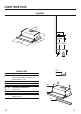
CARATTERISTICHE Ingombro ��� ����� ��� ���� ����� ���� ���� ����� ����� ����� Componenti ��� � Rif. Q.tà 1 1 8 20 1 1 Rif. Q.tà 12a 4 12e 2 Q.
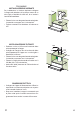
INSTALlAzione Foratura Piano di supporto e Montaggio Cappa MONTAGGIO CON VITI • Il Piano di supporto della Cappa deve essere rientrante di 135 mm dal Piano inferiore dei Pensili. • Forare ø 4,5 mm il supporto utilizzando la Dima di foratura in dotazione. • Praticare un foro ø 125 mm sul Piano di supporto, utilizzando la Dima di foratura in dotazione. • Fissare con 4 Viti 12a (4,2 x 44,4) in dotazione.
Connessioni USCITA ARIA VERSIONE ASPIRANTE Per installazione in Versione Aspirante collegare la Cappa alla tubazione di uscita per mezzo di un tubo rigido o flessibile di ø120 mm, la cui scelta è lasciata all'installatore. ����� • Fissare il tubo con adeguate fascette stringitubo. Il materiale occorrente non è in dotazione. • Togliere eventuali Filtri Antiodore al Carbone attivo. USCITA ARIA VERSIONE FILTRANTE • Praticare un foro ø 125 mm sull’eventuale Mensola soprastante la Cappa.
UsO � ����� � � � � � � ��� � L Luci Accende e spegne l’Impianto di Illuminazione. L Luci Accende e spegne l’Impianto di Illuminazione. M Motore Accende e spegne il motore Aspirazione. M Motore Accende e spegne il motore Aspirazione. V Velocità Determina la velocità di esercizio: V Velocità Determina esercizio: la velocità di 1. Velocità minima, adatta ad un ricambio d’aria continuo particolarmente silenzioso, in presenza di pochi vapori di cottura. 1.
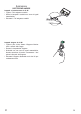
MANUTENzione Filtri antigrasso PULIZIA FILTRI ANTIGRASSO METALLICI AUTOPORTANTI • Sono lavabili anche in lavastoviglie, e necessitano di essere lavati ogni 2 mesi circa di utilizzo o più frequentemente, per un uso particolarmente intenso. • Estrarre il carrello aspirante. • Togliere i Filtri uno alla volta, agendo sugli appositi agganci. • Lavare i Filtri evitando di piegarli, e lasciarli asciugare prima di rimontarli.
Illuminazione SOSTITUZIONE LAMPADE Lampade a incandescenza da 40 W • Togliere i Filtri antigrasso metallici. • Svitare le Lampade e sostituirle con nuove di uguali caratteristiche. • Rimontare i Filtri antigrasso metallici. Lampade alogene da 20 W. • Togliere le due viti che fissano il Supporto illuminazione e sfilarlo dalla Cappa. • Estrarre la Lampada dal Supporto. • Sostituirla con una nuova di uguali caratteristiche, facendo attenzione di inserire correttamente i due spinotti nella sede del Supporto.
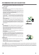
RECOMMENDATIONS AND SUGGESTIONS The Instructions for Use apply to several versions of this appliance. Accordingly, you may find descriptions of individual features that do not apply to your specific appliance. INSTALLATION • The manufacturer will not be held liable for any damages resulting from incorrect or improper installation.
ChARACTERiSTICS Dimensions ��� ����� ��� ���� ����� ���� ���� ����� ����� ����� Components Ref. Q.ty 1 1 8 20 1 1 Ref. Q.ty 12a 4 12e 2 Q.
INSTALLATION Drilling the Support surface and Fitting the Hood SCREW FITTING • The hood support surface must be 135 mm above the bottom surface of the wall units. • Drill the support with a ø 4,5 mm drill bit, using the drilling template provided. • Cut a hole ø 125 mm in size on the support surface, using the drilling template provided. • Fix using the 4 screws 12a (4,2 x 44,4) provided.
Connections Ducting Version AirExhaust System When installing the hood in ducting version, a rigid or a flexible pipe with the diameter corresponding to the flange diameter is used in order to connect the hood to the air outlet piping. ����� • Fix the pipe with an adequate quantity of pipe clamps (not supplied). • Remove possible charcoal filters. ��� Recirculation Version AireOutlet • Cut a hole ø 125 mm in any shelf that may be positioned over the hood.
Use � ����� � � � � � � ��� � L Light Switches the lighting system on and off. L Light Switches the lighting system on and off. M Motor Switches the extractor motor on and off. M Motor Switches the extractor motor on and off. V Speed Sets the operating speed of the extractor: V Speed Sets the operating speed of the extractor: 1. Low speed, used for a continuous and silent air change in the presence of light cooking vapour. 1.
MAINTENANCE Grease filters CLEANING METAL CASSETTE GREASE FILTERS • The filters must be cleaned every 2 months, or more frequently in case of particularly heavy use of the hood. Filters can be washed in a dishwasher. • Pull out the sliding suction panel. • Remove the filters one by one, after having disconnected the relative fastening elements. • Wash the filters, taking care not to bend them. Let them get dry before refitting them.
Lighting LIGHT REPLACEMENT 40 W incandescent light. • Remove the metal grease filters. • Unscrew the bulbs and replace them with new ones having the same characteristics. • Replace the metal grease filters. 20 W halogen light. • Remove the 2 screws fixing the Lighting support, and pull it out of from the Hood. • Extract the lamp from the Support. • Replace with another of the same type, making sure that the two pins are properly inserted in the lamp holder socket holes.
CONSEILS ET SUGGESTIONS La présente notice d'emploi vaut pour plusieurs versions de l'appareil. Elle peut conte-nir des descriptions d'accessoires ne figurant pas dans votre appareil. INSTALlation • Le fabricant décline toute responsabilité en cas de dommage dû à une installation non correcte ou non conforme aux règles de l’art.
CARACTERISTIques Encombrement ��� ����� ��� ���� ����� ���� ���� ����� ����� ����� ��� Composants Ref. Qtè. 1 1 8 20 1 1 Ref. Qtè. 12a 4 12e 2 Qtè.
INSTALlAtion Perçage du Plan de support et Montage de la Hotte MONTAGE AU MOYEN DE VIS • Le Plan de support de la Hotte doit être monté plus en haut de 135 mm. par rapport au Plan inférieur des Armoires murales. • Percer un trou de ø 4,5 mm. sur le support, en utilisant le Gaba-rit de perçage fourni avec l’appareil. • Percer un trou de ø 125 mm. sur le Plan de support, en utilisant le Gabarit de perçage fourni avec l’appareil. • Fixer à l’aide des 4 Vis 12a (4,2 x 44,4) fournies avec l’appareil.
Branchements SORTIE AIR VERSION ASPIRANTE En cas d’installation en version aspirante, brancher la hotte à la tuyauterie de sortie utilisant un tube rigide ou flexible avec le même diamètre de la flasque précé-demment installée. ����� • Fixer le tube par des colliers appropriés. Le matériau nécessaire n’est pas fourni. • Retirer les éventuels filtres anti-odeur au charbon actif. SORTIE AIR VERSION FILTRANTE • Percer un trou de ø 125 mm. sur l’éventuelle Tablette qui se trouve au-dessus de la Hotte.
UTILISATION � ����� � � � � � � ��� � L Allume et éteint l’éclairage. L M Moteur Lumières Allume et éteint le moteur aspiration. M Moteur Allume et éteint le moteur aspiration. V Détermine les d’exploitation ainsi sées: V Détermine les d’exploitation ainsi sées: Vitesses vitesses subdivi- Lumières Vitesses Allume et éteint l’éclairage. vitesses subdivi- 1. Vitesse minimale, pour un rechange d’air perma-nent particulièrement si-lencieux en cas de faibles vapeurs de cuisson. 1.
ENTRetien Filtres anti-graisse NETTOYAGE DES FILTRES ANTI-GRAISSE MÉTALLIQUES AUTOPORTEURS • Les filtres peuvent être également lavés au lavevaisselle; il faut les laver tous les 2 mois d’emploi environ, ou bien plus souvent, en cas d’emploi particulièrement intense. • Sortir le tiroir aspirant. • Retirer un Filtre à la fois, en intervenant sur les crochets spécialement prévus.
Eclairage REMPLACEMENT LAMPES Lampes à incandescence de 40 W • Retirer les filtres anti-graisse métalliques. • Dévisser les lampes et les remplacer par de nouvelles avec les mêmes caractéristiques. • Remonter les filtres anti-graisse métalliques. Lampe halogène de 20 W. • Retirer les 2 Vis qui fixent le Support éclairage et ôter ce dernier de la Hotte. • Extraire la Lampe du Support.
EMPFEHLUNGEN UND HINWEISE Diese Gebrauchsanleitung gilt für mehrere Geräte-Ausführungen. Es ist möglich, dass einzelne Ausstattungsmerkmale beschrieben sind, die nicht auf Ihr Gerät zutreffen. MONTAGE • Der Hersteller haftet nicht für Schäden, die auf eine fehlerhafte und unsachgemäße Montage zurückzuführen sind.
CHARAKTERISTIKEN Platzbedarf ��� ����� ��� ���� ����� ���� ���� ����� ����� ����� Komponenten Pos. St. 1 1 8 20 1 1 Pos. St. 12a 4 12e 2 St.
MONTAGE Bohren der Trägerplatte und Montage der Dunstabzugshaube MONTAGE MIT SCHRAUBEN ��� ��� ��� • Die Hauben-Trägerplatte muss 135 mm oberhalb der Oberschrank-Unterfläche positioniert werden. • Mit Hilfe des beiliegenden Bohrplanes Löcher ø 4,5 mm in die Trägerplatte bohren. • Mit Hilfe des beiliegenden Bohrplanes ein Loch ø 125 mm in die Trägerplatte bohren. • Mit 4 der mitgelieferten Schrauben 12a (4,2 x 44,4) fixieren.
Anschlüsse Anschluss Bei Abluftbetrieb Für die Installation der Haube im Abluftbetrieb mit Hilfe eines Rohres oder Schlauches vom selben Durchmesser wie der zuvor installierte Flansch (ø 150mm, ø 125 mm oder ø 120 mm) am Gebläseaustrittsstutzen anschließen.. ����� • Das Rohr mit geeigneten Rohrschellen fixieren. Das hierzu erforderliche Material wird nicht mitgeliefert. • Eventuell vorhandene Aktivkohlefilter entnehmen.
BEDIENUNG � ����� � � � � � � ��� � L Beleucht. Schaltet die Beleuchtung ein und aus. L M Motor Schaltet den Gebläsemotor ein und aus. M Motor Schaltet den Gebläsemotor ein und aus. V bestimmt die Gebläsegechwindigkeit und steuert fol-gende Geschwindigkeitsstu-fen V bestimmt die Gebläsegechwindigkeit und steuert fol-gende Geschwindigkeitsstu-fen Geschw. Beleucht. Geschw. Schaltet die Beleuchtung ein und aus. 1.
WARTUNG Fettfilter REINIGUNG DER METALLFETTFILTER • Die Filter können im Geschirrspüler gereinigt werden und müssen nach spätestens zwei Monaten Betriebszeit oder, bei besonders intensiver Nutzung, häufiger gereinigt werden. • Den Wrasenleitschirm herausziehen. • Die Verriegelung des Fettfilters zuerst nach hinten, dann nach unten herausnehmen.
Beleuchtung AUSWECHSELN DER LAMPEN Glühlampen 40W • Die Metallfettfilter entfernen. • Die Lampen ausschrauben und durch gleichwertige ersetzen. • Die Metallfettfilter wieder montieren. Halogenlampe 20 W • Vor dem Auswechseln der Lampen, die beiden Schrauben der Lampenhalterung loesen und die Lampenhalterung aus der Dunstabzugshaube ziehen. • Die Lampe aus der Halterung nehmen.
ADVIEZEN EN SUGGESTIES Deze gebruiksaanwijzing geldt voor verschillende uitvoeringen van het apparaat. Het is mogelijk dat er een aantal kenmerken worden beschreven die niet van toe-passing zijn op uw apparaat. INSTALLATIE • De fabrikant aanvaardt geen enkele aansprakelijkheid voor schade die voortkomt uit onjuiste of niet overeenkomstig de regels der kunst uitgevoerde installaties.
EIGENSCHAPPEN Buitenafmetingen ��� ����� ��� ���� ����� ���� ���� ����� ����� ����� Onderdelen Ref. 1 1 8 20 1 1 Ref.
INSTALlAtie Boren van gaten in draagvlak en montage kap MONTAGE MET SCHROEVEN ��� ��� ��� • Het draagvlak van de kap moet 135 mm hoger zijn dan het ondervlak van de hangkastjes. • Boor een gat van ø 4,5 mm in de drager met behulp van de bijgeleverde boormal. • Boor een gat van ø 125 mm in het draagvlak met behulp van de bijgeleverde boormal. • Bevestig met de 4 bijgeleverde schroeven 12a (4,2 x 44,4).
Aansluitingen Luchtuitlaat Afzuigversie In het geval van installatie in afzuigversie, moet u de wasemkap met de uitlaatleiding verbinden door middel van een starre of buigzame leiding die dezelfde diameter heeft als de reeds geïnstalleerde flens. ����� • Zet de leiding vast met geschikte leidingklemmen. Het benodigde materiaal wordt niet bij de wasemkap bijgeleverd. • Verwijder de eventuele geurfilters met actieve koolstof.
GEBRUIK � ����� � � � � � � ��� � L Hiermee schakelt u de erlichting aan en uit. L M Motor Hiermee schakelt u de afzuigmotor aan en uit. M Motor Hiermee schakelt u de afzuigmotor aan en uit. V Instelling van de werkingssnelheid: V Instelling van de werkingssnelheid: Lichten Snelheid Lichten Snelheid Hiermee schakelt u de erlichting aan en uit. 1. Minimumsnelheid, ge-schikt voor een continue en zeer stille luchtverver-sing, als er weinig kook-dampen zijn. 1.
ONDERHOUD Vetfilters REINIGING VAN DE METALEN ZELFDRAGENDE VETFILTERS • Deze filters moeten minstens om de 2 maanden of, bij een bijzonder intensief gebruik vaker, gereinigd worden. Ze kunnen ook in de vaatwasmachine afgewassen worden. • Trek de rolletjes met de zuiggroep naar voren. • Verwijder de filters één voor één door aan de hiervoor bestemde hendeltjes te trekken. • Was de filters zonder ze te vouwen en laat ze drogen alvorens ze weer terug te plaatsen.
Verlichting VERVANGING VAN DE LAMPEN Gloeilampen van 40 W • Verwijder de metalen vetfilters. • Schroef de lampen los en vervang ze door nieuwe lampen met dezelfde eigenschappen. • Plaats de metalen vetfilters terug. Halogeenlamp van 20 W • Verwijder de 2 schroeven waarmee de lamphouder is bevestigd en verwijder de houder uit de kap. • Trek de lamp uit de houder.
www.electrolux.