GAS HOB MODEL ZAF 42 INSTRUCTION BOOKLET 2 Please read this instruction booklet before using the appliance
Important Safety Information You MUST read these warnings carefully before installing or using the hob. If you need assistance, contact our Customer Care Department on 01635 521313 Installation ● This hob must be installed by qualified personnel, according to the manufacturer’s instructions and to the relevant British Standards. ● Any gas installation must be carried out by a registered CORGI installer. ● Remove all packaging before using the hob.
Contents For the User For the Installer Description of the Hob Technical Data Page 10 Page 5 Operation Page 6 Important Safety Requirements Page 11 Installation Page 12 Gas Connection Page 12 Building In Page 13 Electrical Connection Page 14 Wiring Diagram Page 15 Fault Finding Page 16 Commissioning Page 18 Conversion from natural gas to LPG Page 19 Maintenance and Cleaning Page 7 Something Not Working? Page 8 Service and Spare Parts Page 8 Guarantee Conditions Page 9
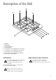
Description of the Hob 3 2 1 3 4 9 1. 2. 3. 4. 5. 6. 7. 8. 9. 8 7 6 5 Hob Top Rapid Burner Semi-rapid Burners Auxiliary Burner Control knob for back right burner (semi-rapid) Control knob for back left burner (semi-rapid) Control knob for front left burner (rapid) Control knob for front right burner (auxiliary) Electric Ignition Push Button INSTALLATION Any gas installation must be carried out by a registered CORGI installer, and in accordance with existing rules and regulations.
Operation HOB BURNERS To light a burner, turn the relevant control knob anticlockwise to maximum position. At the same time push the electric ignition button which is marked with a little spark.. Then adjust the flame as required. If the burner does not ignite, turn the control knob to zero, and try again. i When switching on the mains, after installation or a power cut, it is quite normal for the spark generator to be activated automatically.
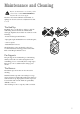
Maintenance and Cleaning Before any maintenance or cleaning can be carried out, you must DISCONNECT the hob from the electricity supply. The hob is best cleaned whilst it is still warm, as spillage can be removed more easily than if it is left to cool. The Hob Top Regularly wipe over the hob top using a soft cloth well wrung out in warm water to which a little wasing up liquid has been added.
Something Not Working? If the hob is not working correctly, please carry out the following checks before contacting your local Zanussi Service Force Centre. IMPORTANT: If you call out an engineer to a fault listed below, or to repair a fault caused by incorrect use or installation, a charge will be made even if the appliance is under guarantee.
Peace of Mind for 24 Months ZANUSSI GUARANTEE CONDITIONS We, Zanussi, undertake that if, within 24 months of the date of the purchase, this Zanussi appliance or any part thereof is proved to be defective by any reason only of faulty workmanship or materials, we will, at our option, repair or replace the same FREE OF ANY CHARGE for labour, materials or carriage on condition that: * The appliance has been correctly installed and used only on the gas and electricity supply stated on the rating plate.
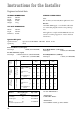
Instructions for the Installer Engineer technical data OVERALL Width: Depth: Height: Weight: DIMENSIONS 580 mm. 500 mm. 88 mm. 8 Kg. SUPPLY CONNECTIONS Gas: RC 1/2 inch (1/2 inch male) Rear right hand corner Electric: 230-240V 50Hz supply, 3 core flexible cable with non rewireable plug fitted with a 3 amp cartridge fuse. CUT OUT DIMENSIONS Width: 550 mm. Depth: 470 mm. Thickness: 30 mm.
Important safety requirements This hob must be installed in accordance with the Gas Safety (Installation and Use) Regulations (Current Edition) and the IEE Wiring Regulations (Current Edition). Detailed recommendations are contained in the following British Standards Codes Of Practice: B.S. 6172/ B.S. 5440, Par. 2 and B.S. 6891 Current Editions. The hob should not be installed in a bed sitting room with a volume of less than 20 m3.
Installation IMPORTANT This hob must be installed by qualified personnel to the relevant British Standards. Any gas installation must be carried out by a registered CORGI installer. The manufacturer will not accept liability, should the above instructions or any of the other safety instructions incorporated in this book be ignored. On the end of the shaft, which includes the GJ 1/2" threaded elbow, adjustment is fixed so that the washer is fitted between the components as shown in the diagram.
Building In Building over a cupboard or drawer ON/OFF SWITCH 2 ON/OFF SWITCH 3 30 1 It is also recommended to carry out the electrical connection to the hob as shown in diagrams 1 and 2. 20 min If the hob is to be installed above a cupboard or drawer it will be necessary to fit a heat resistant board below the base of the hob on the underside of the work surface. a 60 FLEX OUTLET b FLEX OUTLET FO 0763 FO 0764 FO 1013 Dimensions are given in mm.
Electrical connections Any electrical work required to install this hob should be carried out by a qualified electrician or competent person, in accordance with the current regulations. THIS HOB MUST BE EARTHED. The manufacturer declines any liability should these safety measures not be observed. Permanent Connection In the case of a permanent connection, it is necessary that you install a double pole switch between the hob and the electricity supply (mains), with a minimum gap of 3 mm.
Wiring diagram L 1 A 0 2 3 220/240 4 B N A. IGNITOR SWITCH B.
Fault Finding PLUG (with cover removed) Earth Wire Green/Yellow Brown Blue Green Yellow START Isolate appliance and carry out: A: Earth Continuity check. Neutral Wire Blue SOCKET (face view) ( ) E( ) FUSE Preliminary Electrical Systems Check N L Blue Brown Green Yellow NO YES Carry out: C: Polarity check. Has inlet fuse blown? NO YES Carry out: D: Resistance to Earth check. Electricity supply should now be satisfactory. A.
Ignition System / Gas Ignition Ignitor does not spark YES Check gas supply at burner NO Check plug top fuse and replace if necessary Light burner manually Check polarity and earth continuity of supply point Check by pass simmer adjusted Check position of the electrode Check earth continuity of appliance Check continuity from 'N' on the mains connector block and "O" on the ignitor unit Check continuity from the tip of each electrode to the terminals 1 to 4 on the ignitor unit Check continuity fro
Commissioning When the hob has been fully installed it will be necessary to check the minimum flame setting. To do this, follow the procedure below. - Turn the gas tap to the MAX position and ignite. - Set the gas tap to the MIN flame position then turn the control knob from MIN to MAX several times. If the flame is unstable or is extinguished follow the procedure below. Procedure: ☞ Re-ignite the burner and set to MIN. Remove the control knob.
Conversion from Natural Gas to LPG It is important to note that this model is designed for use with natural gas but can be converted for use with butane or propane gas providing the correct injectors are fitted. The gas rate is adjusted to suit. Method • Ensure that the gas taps are in the 'OFF' position • Isolate the hob from the electricity supply • Remove all pan supports, burner caps, rings, crowns and control knobs.