TABLES DE CUISSON KOOKPLATEN KOCHMULDEN HOBS ZAF 2 MODE D'EMPLOI GEBRUIKSAANWIJZING BEDIENUNGSANWEISUNGEN INSTRUCTIONS FOR USE
ENGLISH ☛ For Your Safety These warnings are provided in the interest of safety. You installing or using the appliance. MUST read them carefully before It is most important that this instruction book should be retained with the appliance for future reference. Should the appliance be sold or transferred, always ensure that the book is left with the appliance in order that the new owner can get to know the functions of the appliance and the relevant warnings.
Contents 1. Instruction for the User ............. Pag. 31 5. Electrical Connection ................ Pag. 34 2. Cleaning and Maintenance ....... Pag. 32 6. Adaptation to different types of gas................................ Pag. 35 3. Technical Data ........................... Pag. 32 7. Building In .................................. Pag. 36 4. Instruction for the Installer ....... Pag. 33 Guarantee ................................... Pag. 38 1.
2. Cleaning and Maintenance • Disconnect the appliance from the electrical supply, before carrying out any cleaning or manteinance work. Wash the enamelled components with warm soapy water. Never use abrasive cleaners Frequently wash the "caps" and the "crowns" with hot soapy water, carefully taking away any built-up of food. Carefully wash the stainless steel components with water, then wipe them dry with a soft cloth. The pan supports are dishwasher proof.
4. Instruction for the Installer ● The side walls of the unit in which the hob is going to be installed, must not exceed the height of the working top. ● Avoid installing the appliance in the proximity of inflammable materials (e.g. curtains, tea towels etc.). ● The following instructions about installation and maintenance must be carried out by qualified personnel in compliance with the regulation in force. The regulation to be applied for this type of installation is NBN D 5I.
5. Electrical Connection The appliance is designed to be connected to 230 V monophase electricity supply. The connection must be carried out in compliance with the laws and regulations in force.
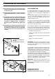
6. Adaptation to different types of gas INJECTORS REPLACEMENT • Remove the pan supports. • Remove the burner's caps and crowns. • With a socket spanner 7 unscrew and remove the injectors (Fig. 7), and replace them with the ones required for the type of gas in use (see table 2). • Reassemble the parts, following the same procedure backwards. • Replace the rating label (placed near the gas supply pipe) with the relevant one for the new type of gas supply.
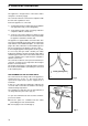
7. Building In A = Auxiliary burner R = Rapid Burner R 510 These hobs can be inserted in a built-in kitchen unit whose depth is between 550 and 600 mm. The hobs dimensions are shown in Fig. 9. A 290 FO 0952 Fig. 9 55 INSTALLATION AND ASSEMBLY These hobs can be installed in a kitchen unit with an opening for insertion whose dimensions are shown in Fig. 10.
Fig. 13 Fig. 12 30 a 60 591 Proper arrangements must be taken in designing the forniture unit, in order to avoid any contact with the bottom of the hob which can be heated when it is operated. The recommended solution is shown in Fig. 12. The panel fitted under the hob should be easily removable to allow an easy access if a technical assistance intervention is needed.
GUARANTEE - SPARE PARTS When calling for repairs during the period of guarantee ofthe appliance, the original invoice or receipt must be shown or sent together with the appliance to be repaired. Extension of the guarantee 7 General conditions of guarantee 1 The manufacturer guarantees the appliance indicated on the relative invoice for a period of one year from the date of purchase.