TABLES DE CUISSON KOOKPLATEN KOCHMULDEN HOBS ZAF 20 MODE D'EMPLOI GEBRUIKSAANWIJZING BEDIENUNGSANWEISUNGEN INSTRUCTIONS FOR USE
INDEX Technical characteristics Page 31 Warnings and useful advice Page 32 Instructions for user Page 33 Instructions for use Page 33 Maintenance and cleaning Page 34 Instructions for installation Electrical connection Page Page 34 35 Insertion in a kitchen unit Page 36 Guarantee and technical assistance Page 39 TECHNICAL DATA DIMENSIONS OF THE OPENING FOR INSERTION (see chapter on assembly) Width: 270 mm Depth: 490 mm Strength of hot plate Back plate: Front plate: Total strength: Vo
IMPORTANT NOTICES AND ADVICE RELATING TO ELECTRIC HOBS It is important that this instruction brochure be kept together with the appliance for future consultation. If the appliance is sold or transferred to another person, ascertain that the brochure is also given, in order that the new owner be aware of the correct use of the apparatus and the relative instructions.
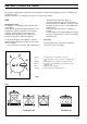
INSTRUCTIONS FOR USER All operations relating to the connection of the hob must be carried out by qualified personnel, according to the regulations in force. Specific instructions are contained in the notices reserved for the installer. USE Control knob of hob The appliance is operated by knobs situated on the control panel. Seven different positions permit the hot plates to be regulated as required. The knobs can be turned clockwise or anti-clockwise.
MAINTENANCE Clean the control panel with a damp cloth, do not use abrasive products. The knobs can be removed by lifting to facilitate cleaning. The enamelled part of the hob can be cleaned with warm water and detergent. Although the enamel will tollerate acids, we advise you to quickly remove splashes of vinigar, lemon and all acid substances. Also immediately remove all residue of fat or other to avoid any incrustation. If incrustations have formed leave the crust immersed in hot water.
REPLACEMENT OF THE VOLTAGE CABLE The connection of the voltage cable to the appliance’s terminal box is of type “Y” which signifies that its replacement requires the specific equipment of a technician. If the replacement of the cable is necessary, use only cables type H 05 VV H2-F O T 105; in both cases, the cables must be of sections suitable to the voltage and able to support the working heat.
INSTALLATION IN A KITCHEN UNIT This hob can be inserted in a fitted kitchen unit with a depth of between 550 and 600 mm and having suitable characteristics. 510 Dimensions (fig. 5) 290 Fig. 5 FO 0959 INSTALLATION AND ASSEMBLY The fixture of the hob to the unit must be carried out as follows: Position the relevant sealings, supplied, on the edge of the opening predisposed for installation, taking care that the edges meet without overlapping.
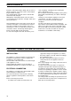
Possibilities for insertion Kitchen unit with oven For the dimensions of the installation see figures 9 and 10. Foresee two brackets for ventilation. a) Removable panel. b) Space possibly useful for fitting. 550 min. 560 min. Kitchen unit with door The unit which will receive the hob should be designed as illustrated in figure 8. The panel under the hob should be easily removable to permit the blocking and unblocking of the hob for technical assistance. 30 FO 0198 30 480 20 min a Fig.
Figures ll-l2 illustrate two possible solutions. The electrical fittings of the oven and the hob must be carried out separately and remain accessible. 50 cm 2 120 cm 2 180 cm 2 360 cm 2 FO 2104 38 Fig. 11 FO 2105 Fig.