85 COOKER Z 8050 WOS Instruction for the use - Installation advice
Dear Customer, We thank you very much for choosing our products. The instructions and advice included in this booklet are given to safeguard your safety and to use this appliance correctly. Be so kind as to keep this booklet. It will be useful to clear any doubt concerning its operation. This appliance must be only assigned to the use for which it has been realized, that is for cooking food. Any other use has to be considered incorrect and therefore dangerous.
IMPORTANT PRECAUTIONS AND RECOMMENDATIONS ● Fire risk! Do not store flammable After having unpacked the appliance, check to ensure that it is not damaged and that the oven door closes correctly. In case of doubt, do not use it and consult your supplier or a professionally qualified technician. Packing elements (i.e. plastic bags, polystyrene foam, nails, packing straps, etc.) should not be left around within easy reach of children, as these may cause serious injuries.
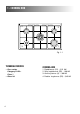
1 - COOKING HOB 2 2 4 3 1 Fig. 1.1 4 TECHNICAL FEATURES COOKING HOB – Gas cooker Category II 2H3+ Class 1 – Glass lid 1. Rapid burner (R1) - 3,15 kW 2. Semi-rapid burner (SR) - 1,90 kW 3. Auxiliary burner (A) - 1,00 kW 4.
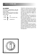
2 - CONTROL PANEL Fig. 2.1 10 9 8 7 6 5 4 3 2 0 0 1 1 1 CONTROLS DESCRIPTION 1. Front right burner control knob 2. Rear right burner control knob 3. Central double-ring burner control knob 4. Rear left burner control knob 5. Front left burner control knob 6. 60’ timer knob 7. Gas oven/gas grill thermostat control knob Pushbuttons: 8. Rotisserie switch 9. Oven light switch 10.
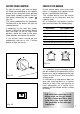
3 - USE OF COOKING HOB GAS BURNERS Each burner is controlled by a gas tap assuring the opening and the closing of the gas supply. Make the symbols printed on the knob to match with the indicator on the control panel to obtain: – symbol 6 ● : off – symbol : full on (nominal rate) – symbol : reduced rate Fig. 3.1 To light one of the gas burners, hold a flame (i.e.
ELECTRIC SPARK IGNITION CHOICE OF THE BURNER To light the burner you have to rotate the knob corresponding to the specific burner to the maximum flame position (large flame symbol) and press the ignition button marked by the symbol (fig. 3.3). The sparks produced by the electrodes situated next to the burner will light the selected burner. On the control panel, near every knob, there is a diagram that indicates which burner is controlled by that knob.
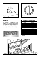
4 - GAS OVEN The glass on the oven door reaches high temperatures during operation. Keep children away. GENERAL FEATURES The oven is furnished completely clean; it is advisable, however, upon first use, to turn the oven on to the maximum temperature (position 10) to eliminate possible traces of grease from the oven burner. The same operation should be followed for grill burner.
1 0 1 2 3 4 5 6 7 8 9 Fig. 4.1 Fig. 4.3 THERMOSTAT THERMOSTAT GRADE TABLE The numbers 1 to 10 printed on the knob (fig. 4.3) indicate the increasing oven temperature value (see table 4.4). To regulate the temperature, set the chosen number onto the control panel indicator (or onto the knob indicator). For efficient oven preheating, we recommend that grill trays and racks are removed from the oven and replaced after about 15 minutes.
OVEN COOKING COOKING EXAMPLES Before introducing the food, preheat the oven to the desired temperature. For a correct preheating operation, it is advisable to remove the tray from the oven and introduce it together with the food, when the oven has reached the desired temperature. Check the cooking time and turn off the oven 5 minutes before the theoretical time to recuperate the stored heat. Temperatures and times are approximate as they vary depending on the quality and amount of food.
IGNITION OF THE GRILL BURNER 1 – Open the oven door to the full extent. WARNING: Risk of explosion! The oven door must be open during this operation. 2 – Light the grill by applying a flame to pipe of the grill burner (fig. 4.6). ATTENTION: Never turn the thermostat before approaching a flame to pipe of the grill burner. 3 – Press in the oven control knob (fig. 4.5) and turn clockwise to the position marked by the symbol . Keep the knob pressed. Never continue this operation for more than 15 seconds.
USE OF THE GRILL USE OF THE ROTISSERIE Very important: the grill must always be used with the oven door ajar (Fig. 4.7). Mount shield “A” which serves to protect the control panel from the heat. Turn on the grill, as explained in the preceding paragraphs and let the oven preheat for about 5 minutes with the door ajar. Introduce the food to be cooked, positioning the rack as close to the grill as possible. The dripping pan should be placed under the rack to catch the cooking juices and fats.
S G H P Fig. 4.8 OVEN LIGHT The cooker is equipped with a light that illuminates the oven to enable visually controlling the food that is cooking. This light is controlled by a switch on the control panel (fig. 4.10). 0 Fig. 4.9 0 1 1 Fig. 4.
5 - MINUTE COUNTER MINUTE COUNTER (Fig. 5.1) The minute counter is a timed acoustic warning device which can be set for a maximum of 60 minutes. The knob (Fig. 5.1) must be rotated clockwise as far as the 60 minute position and then set to the required time by rotating it anticlockwise. 10 50 20 40 30 14 Fig. 5.
6 - CLEANING AND MAINTENANCE GENERAL ADVICE – When the appliance is not being used, it is advisable to keep the gas tap closed. – Every now and then check to make sure that the flexible tube that connects the gas line or the gas cylinder to the appliance is in perfect condition and eventually substitute it if it shows signs of wearing or damage. – The periodical lubrication of the gas taps must be done only by specialized personnel. – If a gas tap jams, do not try to force it. Seek technical assistance.
BURNERS CLEANING They can be removed and washed with soapy water only. They will remain always perfect if cleaned with products used for silverware. After cleaning or wash, check that burnercaps and burner-heads are dry before placing them in the respective housings. All the enamelled parts must be cleaned with a sponge and soapy water or other non-abrasive products. Dry preferably with a soft cloth. Acidic substances like lemon juice, tomato sauce, vinegar etc. can damage the enamel if left too long.
Fig. 6.3 Fig. 6.4 OVEN DOOR STORAGE COMPARTMENT The internal glass panel can be easily removed for cleaning by unscrewing the 4 retaining screws (Fig. 6.3) The storage compartment is accessible through the pivoting panel (fig. 6.4). Do not store flammable material in the oven or in the storage compartment.
REMOVING THE OVEN DOOR The oven door can easily be removed as follows: Fig. 6.5A – Open the door to the full extent (fig. 6.5A). – Attach the retaining rings to the hooks on the left and right hinges (fig. 6.5B). – Hold the door as shown in fig. 6.5. – Gently close the door and withdraw the lower hinge pins from their location (fig. 6.5C). Fig. 6.5B – Withdraw the upper hinge pins from their location (fig. 6.5D). – Rest the door on a soft surface.
ASSEMBLY AND DISMANTLING OF THE SIDE RUNNER FRAMES – Fit the side runner frames into the holes on the side walls inside the oven (Fig. 6.6). – Slide the tray and rack into the runners as shown in Fig. 6.7. – To dismantle, operate in reverse order. OVEN FLOOR The oven floor “F” (fig. 6.8) can be easily removed to facilitate cleaning. Remember to replace the floor correctly afterwards. Be careful not to confuse the tray “L” with the oven floor “F”. L F Fig. 6.6 Fig. 6.7 Fig. 6.
Advice for the installer IMPORTANT – The appliance must be installed by a licensed electrician in compliance with the laws in force in your country and in observation of the instructions supplied by the manufacturer. – Cooker installation, regulation and conversion to other gas types must only be carried out by QUALIFIED TECHNICIANS. Failure to observe this rule will invalidate the warranty. – The electrical mains outlet, if located behind the cooker, must not be higher than 18 cm above the floor level.
7 - INSTALLATION INSTALLATION The cooker afford class ‘1’ protection against overheating surrounding surfaces. A space of at least 2 cm must be left between the cooker and any adjacent furniture, which must not exceed the height of the cooktop (fig. 7.1). 500 mm 800 mm The surfaces of adjacent furniture must be capable of withstanding temperatures up to 75˚C. 500 mm 300 mm m 20 m Fig. 7.
FITTING THE ADJUSTABLE FEET The adjustable feet must be fitted to the base of the cooker before use. Rest the rear of the cooker on a piece of the polystyrene packaging exposing the base for the fitting of the feet. Fig. 7.2 Fit the 4 legs by screwing them tight into the support base as shown in picture 7.3. WARNING When raising cooker to upright position always ensure two people carry out this manoeuvre to prevent damage to the adjustable feet (fig. 7.4). Fig. 7.3 22 Fig. 7.
WARNING Be carefull: DO NOT LIFT the cooker by the door handle when raising to the upright position (fig. 7.5). Fig. 7.5 WARNING When moving cooker to its final position DO NOT DRAG (fig. 7.6). Lift feet clear of floor (fig. 7.4). Fig. 7.6 LEVELLING THE COOKER The cooker may be levelled by screwing the lower ends of the feet IN or OUT (fig. 7.7) Fig. 7.
CHOOSING SUITABLE SURROUNDINGS Extractor hood for products of combustion H min 650 mm In the room chosen to accommodate the gas appliance, there must be an adequate natural draft to allow combustion of the gas. The natural draft must be produced directly by one or more vents made in the external walls and providing a total opening of at least 100 cm2. If the appliance does not have a noflame safety device this opening must have an area of at least 200 cm2.
8 - GAS SECTION The walls adjacent to the cooker must be of material resistant to heat. If the appliance must be operated with a gas different than that indicated on the plate, it is necessary to execute the following operations: – Gas connection GASES The gases used for the operation of cooking appliances may be grouped by their characteristics into two types: – G20 – G30 / G31 INSTALLATION The connection must be executed by a qualified technician according to the relevant standards.
These operations must be carefully fulfilled as follows. GAS CONNECTION – Connect the cooker to the gas mains utilizing rigid or flexible pipes. – The connection must be executed to the rear of appliance (left or right) (fig. 8.1); the pipe do not cross the cooker. – The unused end inlet pipe of the cooker (left or right) must be closed with the plug interposing the gasket. Gas connection for: Cat: II 2H3+ The fitting (fig. 8.
REPLACEMENT OF THE TOP INJECTORS IMPORTANT: To replace the adapters it is necessary to operate with 2 spanners (fig. 8.3). To replace the injectors, raise the cooktop in the following manner: – Pull the lid “A” upwards to remove from the cooker. – Remove the pan supports and burners from the cooktop. – Remove the 4 screws “B” and the central screw “C” (fig. 8.4a - fig. 8.4b). – Remove the two hinge brackets “D” by pulling them upwards. – Raise the cooktop in the direction shown by the arrow “E”.
TABLE FOR THE CHOICE OF THE INJECTORS Cat: II 2H3+ Auxiliary (A) Semirapid (SR) Rapid Double-ring Oven Grill BURNERS Auxiliary (A) Semirapid (SR) Rapid Double-ring Oven Grill Nominal power [kW] Reduced power [kW] 1,00 1,90 3,15 3,45 5,00 4,00 0,30 0,38 0,60 0,85 1,10 – Nominal power [kW] Reduced power [kW] 1,00 1,90 3,15 3,45 5,00 4,00 0,30 0,38 0,60 0,85 1,10 – G 30 / G 31 28-30/37 mbar By-pass [1/100 mm] Ø injector [1/100 mm] Tube ring opening [mm] 27 29 39 47 53 – 50 67 86 92 107 98 3* 5,
REPLACEMENT OF THE TOP INJECTORS (Fig. 8.5) – Loose the screw “M” of each injector and fully raise the adjusting air tube “A”. – By a polygonal 7 spanner, remove the injector “J” from their housing and replace it by the proper one according to the kind of gas (see injectors table).
OVEN BURNER AND GRILL BURNER REPLACEMENT OF INJECTORS a) oven burner – Lift and remove the lower panel inside the oven. – Unscrew and remove the burner securing screw A (fig. 8.7). – Slacken screw B (fig. 8.7). – Withdraw the burner in the manner shown in figure 8.8, and rest it inside the oven. Take care not to damage the wire to the safety valve probe. – Using a 10 mm box spanner, unscrew the injector (indicated by the arrow in fig. 8.
b) grill burner – Unscrew and remove the burner securing screw ‘C’ (fig. 8.9). – Slacken screw ‘D’ (fig. 8.9). – Move the burner in the manner shown in figure 8.10. Take care not to damage the wire to the safety valve probe. – Using a 10 mm box spanner, unscrew the injector (indicated by the arrow in fig. 8.10) and replace with a new injector selected in accordance with the “TABLE FOR THE CHOICE OF THE INJECTORS”; then replace the burner repeating the above steps in reverse order. C Fig. 8.9 Fig. 8.
Fig. 8.11 Using a cross-head screwdriver, slacken the screw securing the air flow regulation collar (fig. 8.11 and 8.12) and move the collar forward or backward to increase or reduce the air aperture in accordance with gas type and the indications in the “ TABLE FOR THE CHOICE OF THE INJECTORS”. Light the burner and check the flame. 32 Fig. 8.
ADJUSTMENT OF THE OVEN BURNER MINIMUM This needs to be done only for the oven burner (the grill is a fixed capacity) by acting on the thermostat in the following way: – turn on the burner by setting the thermostat knob on position 10 – unscrew the by-pass screw (fig. 8.13) about three times by a flat screwdriver – let the oven heat up for about 10 minutes, then bring the thermostat to position 1 (minimum) to operate the thermostat by-pass – slowly screw the by-pass screws “G” (fig. 8.
9 - ELECTRICAL SECTION IMPORTANT: The cooker must be installed in accordance with the manufacturer’s instructions. Incorrect installation, for which the manufacturer accepts no responsibility, may cause damage to persons, animals and things. GENERAL N.B. For connection to the mains, do not use adapters, reducers or branching devices as they can cause overheating and burning.
ELECTRICAL FEEDER CABLE CONNECTION FEEDER CABLE SECTION TYPE HO5RR-F To connect the supply cable: - Remove the screws securing the cover “A” on the rear of the cooker (fig. 9.1). 3 x 0,75 mm2 230 V - Feed the supply cable through the cable clamp “D”. The supply cable must be of a suitable size for the current requirements of the appliance; see the section “Feeder cable section” (fig. 9.1). 230 V - Connect the wires to the terminal block “B” as shown in the diagram in figure 9.
The manufacturer cannot be held responsible for possible inaccuracies due to printing or transcription errors in the present booklet. The manufacturer reserves the right to make all modifications to its products deemed necessary for manufacture or commercial reasons at any moment and without prior notice, without jeopardising the essential functional and safety characteristics of the appliances. Cod.