Contents Installation Location Page 4 Electrical connection Page § Operation Sorting and loading the laundry Page 7 Selecting the drying programmed Page 8 Starting Page 8 Drying programmed Page 9 Stopping Page 10 Maintenance Cleaning the filter Page 10 Cleaning the dampness Page 10 Control sensors Page 10 Some useful hints Page 10 Something not working Page 11 Directions for the installer Page 12 Technical data Width Depth Height Capacity Supply voltage Power adsorbed: motor ventilator heating element Total
Installation Location Install the appliance in a well ventilated room or having at any rate 4 window facing directly outside. This will allow the machine to vent the steam that builds up during operation directly into the outside. Depending on your requirements, the stern-vent-can-be-positioned-either at the rear or side of the appliance (Fig. 1} The unused outlet should be ed by means of the special cover supplied with the appliance (Fig, 2).
Electrical connection WARNING: THIS APPLIANCE MUST BE EARTHED The manufacturer declines any ability should this safety measure not be ch served. If the plug that is {pitted o your appliance is not suitable for your socket outlet, it must be but off and the appropriate plug fitted. The eut off plug should be disposed of to prevent the hazard of electric shocks in case it should be plugged into a 13 Amp socket in another part of your home.
Operation Control panel 1. Drying time selector 2. Start and stop switch 3. Operating pilot lamp 4.
Sorting and loading the laundry Open the loading door by pulling the stall handle outwards, Before using the appliance for the first time, clean the inside of the drum with a piece of cloth slightly soaked in a fettle alcohol. Sort, the Laundry according to type of fabric (this sorting operation will already have been done if you are using a washing machine for your laundering). So all you have transfer your washed and spin-dried laundry from the drum of the washing machine to the drum of the dryer.
Inflecting and electronic control programmer By means of the electronic control circuit incorporated in this machine, drying of the laundry is automatically controlled. This special feature operates independently of the quantity of laundry loaded in the drum and its dampness, All you have set the programmer selector knob onto the letter corresponding to the type of laundry to be dried and to the degree of drying required.
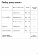
Drying programmed Type of laundry Degree of drying required Quantity nimble Cupboard dry Max. 10 Tbs A Cotton and linen | Hand ironing dry Max. 10 s B Machine ironing dry Max. 10 Ibs C Synthetics Cupboard dry Max. 4 Tbs D Delicate synthetics | Cupboard dry Max.
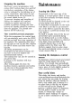
Stopping the machine Electronic control programmed; with eyeless A-B-C {cotton, linen ete) and D-F {synthetics), completion of the drying eyelet is indicated by the lighting up of eyelet completions pilot lamp (4) and by a buzzing given off at intervals by the sound signal device (5). To prevent creasing and rumpling of fabrics, the tumbler will continue rotating at regular intervals for a number of minutes, During this time interval all laundry should be removed from the machine.
50065 Fig | Something not working... If any malfunction is detected, cheek the following points in an floret to remove the trouble, if at all possible: #® The machine will not start; Check the following points: is the loading door correctly closed; is the plug correctly inserted into the wall socket; the fuses of the electric installation are not blown.
Directions for the installer Fixed steam vent installation Fittings to be used: Plastic hose with 100 mm dia. Remove the ring nut (A Fig. 7) from the exhaust connector of the machine. Resew it on to the end of the hose and refit the resulting emblem to the steam vent connector of the machine. Stacked installation (kit CN1) Remove the work top from the washing machine by unscrewing the rear fixing SLEWS, Fix protection panel B as shown in Fig.
o Fig. 10 Fig. 1t ol Fig. 12 Stacked installation (kit CN2) (with pull-out tale} 1. To take off the cabinet top, fist remove the two rear fixing screws, then slide it through the side joints. 2. Remove the two plastic blocks A Fig. 10. 3. Fit the protection panel B as shown in Fig. 10 and fix it by means of the plastic blocks "ig. 10 supplied. 5. Remove the four leveling feet from the dryer, 6. Fit the two runners I at the base of the dryer as in Fig. 11. 7. Elide table B into the runners. 8.
Mounting instructions (kit CN3) This kit allows stacking of a dryer on top of washer 60 em. large. Operate as followings: Assemble the pieces as shown in Fig. 18 using the screws with washer. Mount the unit under the tumble dryer, using the 6 self tapping screws (Fig. 14). Stack driver on top of washer. Resew in screws «A» to obtain a firm union of the two appliances through clamps «B». Important: Each appliance must be connected to an independent. electrical socket. 14 oeE Fig.
GAUSSIAN APPLIANCE GUARANTEE GAUSSIAN STANDARD GUARANTEE CONDITIONS This guarantee is in addition to your statutory and other legal rights which will not be excluded ar in any way diminished by the return of the guarantee card.