ir33 platform ir33 ir33 power ir33 DIN powercompact powercompact small mastercella User manual
User manual
ENGLISH IMPORTANT WARNINGS CAREL bases the development of its products on decades of experience in HVAC, on the continuous investments in technological innovations to products, procedures and strict quality processes with in-circuit and functional testing on 100% of its products, and on the most innovative production technology available on the market.
1. INTRODUCTION ENGLISH Content 7 1.1 Main features ............................................................................................................................................................. 7 2.1 Display ........................................................................................................................................................................ 9 2. USER INTERFACE 9 2.2 ir33, ir33 power and ir33DIN keypad ...................................................
ENGLISH 7. DESCRIPTION OF THE OPERATING PARAMETERS 34 7.1 Temperature probe management parameters .......................................................................................................... 34 7.2 Temperature control parameters................................................................................................................................ 36 7.3 Compressor management parameters ..................................................................................................
ENGLISH 1.
ENGLISH HACCP This function, increasingly required in the refrigeration market, is included as standard on all models with clock. This allows the monitoring of critical points by measuring and recording the temperatures in the event of high temperature alarms or power failures. Up to 3 high temperature alarms and 3 alarms corresponding to power failures can be saved.
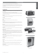
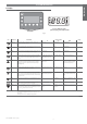
ENGLISH 2. USER INTERFACE 2.1 Display ir33, ir33 DIN, ir33 power, powercompact, powercompact small MasterCella Fig. 2.a ICON FUNCTION DESCRIPTION Normal operation OFF ON COMPRESSOR ON when the compressor starts. Flashes when the activation of the compressor is delayed by safety times. FAN Compressor off Awaiting activation ON when the fan starts.Flashes when the activation of the fan is prevented Fan on due to external disabling or procedures in progress.
ENGLISH 2.2 ir33, ir33 power and ir33DIN keypad 4 6 6 8 4 7 8 7 ir33 DIN ir33, ir33 power Fig. 2.b Icon Normal operation pressing the button alone Start up Automatic address assignment request pressing together with other buttons If pressed for more than 5 seconds, accesses the menu PRG+SET: if pressed together for more than 5 seconds, accesses the If pressed for more than 5 seconds If pressed for more than 1 second, for setting the type “F” parameters (frequent).
3 5 2 1 6 8 4 1 7 MasterCella 2 3 4 5 6 7 ENGLISH 2.3 powercompact, powercompact small and MasterCella keypad 8 powercompact, powercompact small Fig. 2.
ENGLISH 3. INSTALLATION To install the controller, proceed as follows, with reference to the connection diagrams shown in the manual on electrical specifications and connections: 1. connect the probes and power supply: the probes can be installed up to a maximum distance of 10 m from the controller, using shielded cables with a minimum cross-section of 1mm2. To improve the immunity to disturbance, use probes with shielded cables (connect only one end of the shield to the earth on the electrical panel). 2.
ENGLISH 4. PROGRAMMING THE INSTRUMENTS The operating parameters can be modified using the front keypad, and are divided into two families: frequent use parameters (type “F”) and configuration parameters (type “C”). Access to the configuration parameters is protected by a password that prevents unwanted modifications or access by unauthorised persons.
4.4 Displaying and setting the set point ENGLISH 1. Press SET for more than 1 second to display the set point; 2. increase or decrease the set point using the or buttons respectively, until reaching the desired value; 3. press SET again to confirm the new value. 4.5 Alarms with manual reset The alarms with manual reset can be reset by pressing PRG and ptogether for more than 5 seconds, if the causes are no longer present. 4.
ENGLISH 5. ACCESSORIES 5.1 Parameter copying key Programming keys PSOPZKEY00/A0 The programming keys PSOPZKEY00 (Figure 5.a) and PSOPZKEYA0 (Figure 5.b) are used to copy the complete set of parameters relating to the CAREL ir33 controller parameters, but not the 6 sets of customisable default parameters. The keys must be connected to the connector (4 pin AMP) fitted on the compatible controllers, and work even without switching the controller on.
5.2 Remote control ENGLISH The compact remote control with 22 buttons, allows direct access to the following parameters (Fig. 5.f): • temperature; • defrost; • fans; • alarms; • HACCP. The following functions can also be controlled: • start defrost; • AUX; • light; • ON/OFF; • mute. The standard remote control features the four buttons, PRG/mute, SET, UP and DOWN, which access almost all the functions provided by the instrument keypad.
The RS485 serial card option (IROPZ48500), shown in Figure 5.l, allows the ir33 instrument to be connected to the RS485 serial network for supervision. In addition, the serial interface option IROPZ485S0 is available, with automatic recognition of the polarity (+ and -). For further details, refer to the corresponding instruction sheet. Fig. 5.l 5.
5.9 Terminals (MasterCella) ENGLISH This accessory is used to group together the neutral, live and earth connections on a single board installed inside the mastercella. There are two models available: with 3 and 5 rows of terminals. In particular, the second accessory allows direct access with the cables from the loads (live, neutral and earth) to this board alone, thus avoiding having to make the connections during installation to the support terminal block on the mastercella.
ENGLISH 6. DESCRIPTION OF THE FUNCTIONS 6.1 Models Below is a list of the functions relating to the various models of controller.
6.3 Switching the controller ON and OFF ENGLISH The unit can be switched ON/OFF from a number of sources; keypad, supervisor and digital input. In this operating mode, the display will be show the temperature selected for parameter /tI, alternating with the OFF message. The digital input can be used to switch the controller on/off, setting parameter A4/A5/A9 to “6”. Switching on/off from digital input has priority over the same function from the supervisor and from the keypad.
6.4 Auxiliary output management Button Supervisor Digital input Time band ENGLISH The auxiliary output can be controlled by a number of sources: button, supervisor, digital input, and time band. The AUX is switched on and off in the following events: Aux Action pressing the button variation in value from the supervisor change in the status of the contact (opening/closing) according to day, hour, minutes for switching on/off Tab. 6.
ENGLISH • • • • immediate alarm from external digital input (A4, A5, A9), as this delays compressor activation; alarm delayed by time (A7) from external digital input (A4, A5, A9) as this delays compressor activation; high condenser temperature alarm (only with hot gas defrost), as this delays compressor activation opening the door (only with hot gas defrost if the compressor has the door management algorithm). 6.6.
6.6.7 Dripping ENGLISH The dripping time is set by parameter dd, when the compressor is OFF and the fans are OFF. At the end of dripping time, the postdripping phase starts with the fans OFF (Fd): • the compressor restarts normal operation; • the fans remain off. If the post-dripping time with fans OFF is set to zero, normal control is resumed directly. 6.6.8 Post-dripping (fans OFF) The post-dripping time with fans OFF is set by parameter Fd.
ENGLISH 6.7 New defrost activation modes 6.7.1 Defrost according to compressor running time To enable the controller for this operating mode, set a value >0 for parameter d10. This mode affects the start defrost, that is, according to the evaporator temperature (parameter d11), the controller checks the compressor running time (parameter d10) and decides whether to activate the defrost or not.
6.7.3 Defrost at intervals calculated according to the duration of the previous defrost: Skip defrost ENGLISH To enable the controller for this operating mode, set the parameter d12=2. In this case, according to the duration of the last defrost operation, the controller establishes whether the next defrost is skipped or not.
6.8 Pump down and low pressure ENGLISH 6.8.1 Enabling the function The pump down function is activated by setting parameter c7 (pump down duration) to any value other than zero. The pump down valve must be connected to the auxiliary output, setting the relevant parameter (H1). In addition, one of the digital inputs (A4, A5, A9) must be set as a low pressure input. 6.8.
6.9.2 Continuous cycle in progress ENGLISH When the continuous cycle is running: • the compressor is always ON; • the low temperature alarm is deactivated; • the icon is on steady. If, during the continuous cycle, the door is opened and one of the digital inputs is set to manage the opening of the door, the compressor stops and consequently the continuous cycle is temporarily interrupted.
6.10 High condensing temperature alarm ENGLISH If a probe is set as a condenser probe (/A2, /A3, /A4, /A5), the condensing temperature can be monitored and a high temperature condition signalled, probably due to situations of fouling and obstruction. If no condenser probe is selected, the condenser prealarm and alarm are disabled. The condenser fan output, if selected, is always OFF.
Control with dead band can be activated by using the aux1 or aux 2 output for the reverse step: H1 or H5=11. The set point ‘St’ is in the centre of the dead band. The parameter ‘rd’ represents the control differential associated with the compressor, ‘rn’ the size of the dead band, ‘rr’ the differential for reverse control associated with the aux1 or aux 2 output. The diagram in Figure 6.d shows control with dead band in the case of direct operating mode (‘r3’=0 and 1).
6.12 Control with second step Direct Control with a second step can be activated, using the aux1 or aux 2 output,‘H1 or H5’=12 or 13 (with selection of rotation). The set point for the second step is equal to the sum of the set point ‘St’ and the parameter ‘rd’/2, which represents the differential. Control in reverse mode is possible for the second step in the same way as for the first ( parameter r3, digital input), therefore three steps are possible in reverse (with dead band control).
6.
Function active ENGLISH Door switch with compressor, fan off, no light management Door switch with compressor off, no light management Light activation from keypad or supervisor Auxiliary activation from keypad or supervisor Alarms Virtual control probe alarm Product probe alarm Defrost probe alarm Condenser probe alarm Antifreeze probe alarm Function in antifreeze Normal operation Normal operation Normal operation Normal operation See table of alarms and signals Normal operation Normal operation Normal
6.16 HACCP (Hazard Analysis and Critical Control Point) ENGLISH This function can only be activated on the controllers with the RTC option fitted, and allows advanced control of the operating temperature and the recording of any anomalies due to power failures or increases in the operating temperature due to various causes (breakages, severe operating conditions, operator errors, etc…). There are two types of HACCP alarm, signalled on the display with the following codes respectively: HA and HF.
ENGLISH 7. DESCRIPTION OF THE OPERATING PARAMETERS 7.
ENGLISH Example: if the room probe is in intake mode, and probe 2 in outlet mode, control can be performed based on the weighted average of the 2 values read. The formula used is: probe average (Virtual probe) = [S1 x (100 - P) + (S2 x P)] / 100 where: S1 = room probe; S2 = probe 2; P = value of the parameter /4.
ENGLISH /A2: Configuration of probe 2 Used to configure the operating mode of probe 2. /A2= 0 => probe 2 absent /A2= 1 => product probe (used for display only) /A2= 2 => defrost probe /A2= 3 => condenser probe /A2 = 4 => antifreeze probe In any case, probe 2 is used for calculating the virtual control probe. Default: /A2= 2 => defrost probe; /A2= 0 on models M and S => probe 2 absent. /A3: Configuration of probe 3 As above, but relating to probe 3.
ENGLISH Note: • the step associated with the aux 1 or 2 output is only associated with the protection timer c0, while the step associated with the compressor (in both direct and reverse operation) is associated with the timers c0, c1, c2, c3.
7.3 Compressor management parameters ENGLISH ON accensione strumento power ON OFF ON richiesta di intervento insertion request Code c0 c1 c2 c3 c4 cc c6 c7 c8 c9 c10 c11 OFF ON compressore compressors OFF C0 Fig. 7.
ENGLISH cc: Continuous cycle duration This is the time (in hours) during which the compressor operates continuously to lower the temperature, even below the set point. With cc=0 => the continuous cycle is disabled. The controller exits the continuous cycle procedure after the time set for parameter cc has elapsed, or upon reaching the minimum specified temperature (see the minimum temperature alarm, parameter AL). Default: cc=0 (hours).
ENGLISH 7.4 Defrost management parameters Code d0 dI dt1 dt2 dt3 dP1 dP2 d3 d4 d5 d6 dd d8 d8d d9 d/1 d/2 dC dC1 d10 d11 d12 dn dH Parameter Type of defrost Interval between defrosts End defrost temperature, evaporator End defrost temperature, aux evap. End defrost temperature, evap. probe 3 Maximum defrost duration, evaporator Maximum defrost duration, aux evap.
ENGLISH dt2: end defrost temperature set point, auxiliary evaporator dt2 acts in the same way as parameter dt1 described above, but referring to the auxiliary evaporator. Note for dt1 and dt2: in the defrost by temperature, the parameter establishes the threshold for activating or deactivating the corresponding defrost relay. Default: dt2 =4°C. ‘dt3’: end defrost temperature SET POINT, probe 3 (hidden parameter) This parameter is used to set the end defrost temperature measured by the third defrost probe.
ENGLISH d6: Display during defrost Specified values: • d6=0 => during the defrost the instrument displays the text dEF alternating with the value read by the probe selected using parameter /tI. This is to signal that any high temperature values are due to the defrost procedure in progress. • d6=1 => during the defrost the last temperature shown before the start of the cycle remains on the display.
d12 0 1 2 3 Skip defrost ENGLISH d12: Advanced auto-adapting defrosts This parameter is used to enable and disable the advanced defrost function, as per the following table: Automatic variation of dI Disabled Disabled Enabled Enabled Disabled Enabled Disabled Enabled Tab. 7.f Default: d12 =0 => Both the functions are disabled. dn: Nominal defrost duration This indicates the average duration of the defrost in normal operating conditions.
ENGLISH Warnings for using the continuous cycle The low temperature alarm is also used in the continuous cycle (see the description of parameter cc’. In fact, if the temperature falls to the alarm level, the continuous cycle is stopped automatically, even if the selected time has not yet elapsed. This deactivation, however, does not involve an alarm signal. Default: AL =0 => low temperature alarm disabled. Note: for the control probe alarm, the low temperature alarm is reset and monitoring reinitialised.
ENGLISH • both the immediate and delayed external alarm have automatic reset; • if more than one digital input is configured as the delayed alarm, the alarm will be generated when at least one of the inputs is open; • if control with two compressor steps is selected (with or without rotation, H1, H5 = 12 or 13) the delayed external alarm acts on both steps.
ENGLISH If after the door is first closed the light is switched off manually, the controller resumes normal operation. Note: 1. if the light was previously switched on manually, when the door is closed for the second time, it is automatically switched off ; 2. if more than one digital input is configured as the door switch, the door open status will be considered when at least one of the inputs is open; 3.
ENGLISH In the first case, , the sensor signals the opening and the closing of the door, because, with the door open, light is signalled, and with the door closed, darkness is signalled (the sensor is located in the door stop and thus will be shadowed when the door is closed). The inside light will be automatically switched on when the door is open and switched off when the door is closed. The light stays OFF for a minimum time of 5 seconds, to avoid rapid, successive impulses of the light relay.
ENGLISH A7: Delay in detecting the external alarm (multifunction input) Establishes the delay (in minutes) in detecting an external alarm, if selected as a delayed external alarm (A4, A5=2) or the signal of the low pressure (LP) alarm). Note: if A7= 0, in the event of delayed alarms from digital input (A4 or A5 or A9= 2), the controller does not act on the control outputs.
Allarme “CHt” e off refrigerazione (ripristino manuale) “AC” - “AE”/2 “Ac-AE” AdF: Antifreeze alarm delay. Sets the delay for detecting the antifreeze alarm. Default: AdF= 1. “Ac” temp. condensatore Preallarme solo visualizzazione allarme “cht” (ripristino automatico) Fig. 7.m ON “Ac” Fig. 7.n ir33 +030220441 - rel. 2.5 - 16.06.10 49 “AE” temp. condensatore ENGLISH ALF: Antifreeze alarm threshold Defines the temperature value below which the antifreeze alarm is detected, with the message AFr.
ENGLISH 7.6 Fan management parameters Code F0 F1 F2 F3 Fd F4 F5 Parameter Fan management Fan start temperature Fan OFF with compressor OFF Fans in defrost Fan OFF after dripping Condenser fan stop temperature Condenser fan start differential Models ---F ---F ---F ---F ---F MSYF MSYF UOM flag °C/°F flag flag min °C/°F °C/°F Type C F C C F C C Min 0 -50 0 0 0 -50 0.1 Max 2 200 1 1 15 200 20 Def. 0 5.0 1 1 1 40 5.0 Tab. 7.
In the event of condenser probe errors, the condenser fan output, if selected, is activated. Important: If no condenser probe is selected, the condenser fan output, if selected, is disabled. Default: F4=40.0 degrees. F5: Condenser fan start differential This is the differential used to control the condenser fans. Default: F5=5.0. “F4” + “F5” temp. condensatore “F4” 0.2 prima accensione Fig. 7.p 7.
ENGLISH H2: Disable keypad and/or remote control Parameter ‘H2’ can be used to inhibit some functions relating to the use of the keypad, for example, the modification of the parameters and the set point if the unit is accessible to the public.
ENGLISH H8: Select light or AUX output to activate with time band. This parameter can be used to select the output that is activated or deactivate according to the time band (see parameters tON and tOF). H8=0=> Time band linked to output configured as the light. H8=1=> Time band linked to output configured as AUX. Note: the output being controlled (light or AUX) must be available and selected with parameter H1. Default: H8=0 => Time band linked to the light. H9: Enable set point variation with time band.
ENGLISH In: select normal, master or slave unit (masked parameter). The parameter In establishes whether the unit is normal, master or slave. The maximum number of slaves in a sub-network is 5. • Normal: stand-alone unit • Master: Master unit. Allows the synchronisation of the defrosts, remote signalling of the light and aux relays and the alarms, and the downloading of the parameters. • Slave: Slave unit. Unit part of a local network serving the master.
7.
ENGLISH 7.
C C C C C C C C C C C C C 0 0 0 0 0 0 0 0.0 0.1 0 0 -50 0 14 14 100 250 1 14 1 200 20 250 250 200 15 3 0 0 0 0 0 0 70.0 10.0 0 0 -5.0 1 Parameter Fan management Fan start temperature Fan OFF with compressor OFF Fans in defrost Fan OFF after dripping Condenser fan stop temperature Condenser fan start differential Model ---F ---F ---F ---F ---F MSYF MSYF UOM flag °C/°F flag flag min °C/°F °C/°F Type C F C C F C C Min 0 -50 0 0 0 -50 0.1 Max 2 200 1 1 15 200 20 Def. 0 5.0 1 1 1 40 5.
ENGLISH d__ h__ n__ tc y__ M__ d__ u__ h__ n__ Day Hours Minutes RTC date/time setting Year Month Day of the month Day of the week Hours Minutes **** **** **** MSYF **** **** **** **** **** **** Days Hours Min. Years Months Days Days Hours Min.
8.1 Summary table of alarms and signals: display, buzzer and relay The following table describes the alarms and signals on the controller, with their description, the status of the buzzer, the alarm relay and the reset mode.
ENGLISH 8.2 Table of alarms and signals: functions enabled/disabled The following table highlights the functions that are enabled and disabled in the various alarm situations.
ENGLISH NOTE: ir33 +030220441 - rel. 2.5 - 16.06.
ENGLISH NOTE:
CAREL INDUSTRIES HQs Via dell’Industria, 11 - 35020 Brugine - Padova (Italy) Tel. (+39) 049.9716611 - Fax (+39) 049.9716600 e-mail: carel@carel.com - www.carel.com +030220441 rel. 2.5 - 16.06.