
User manual


8
Gas Burners Rating
Rapid Burner 2.45 kW
Auxiliary Burner 0.95 kW
Semi-rapid Burner 1.60 kW
Appliance Class 3
Appliance Category I3
Appliance Gas Supply LPG 30 mbar
Gas connection RC 1/2 inch (1/2 inch male)
Electric Supply 230 V 50 Hz
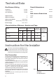
A) End of shaft with nut
B) Washer
C) Adjustable joint
Fig. 4
FO 1010
Technical Data
Instruction for the Installer
Overall dimensions
Width 750 mm
Depth 510 mm
Hob recess dimensions
Length 560 mm
Width 480 mm
Burner Nominal Power
LPG (Butane"A")
Diameter Feeding
Tap. By-Pass Pressure
kW kCal/h Nozzle g/h mbar (*)
Auxiliary 0.95 814 50 75 28
Semi-rapid 1.60 1368 65 126 35 30
Rapid 2.45 2095 80 193 45
Characteristics of Burners, Nozzles and Taps
This hob must be installed by qualified personnel.
The manufacturer will not accept liability, should
the above instructions or any of the other safety
instructions incorporated in this book be ignored.
Gas Connection
On the end of the shaft (A), which includes the GJ 1/2"
threaded elbow, an adjustable joint is fixed so that the
washer (B) is fitted between the components as shown
in the diagram (Fig. 4).
A drop of paint at both edges of the "L" joint (C) will
evidence that the good seal of the connection has been
tested in the factory.
Before connecting the gas supply pipe to the joint (C),
the installer will ensure that the paint drop is unbroken
and the "L" connector has not been removed by the
vibrations during handling and transportation.
When the final connection has been made, it is essential
that a thorough leak test is carried out on the hob and
installation.
Ensure that the main connection pipe does not exert
any strain on the hob.
(*) 1 mbar = 10 mm. water column