
User manual


11
Electrical connections
Any electrical work required to install this hob
should be carried out by a qualified electrician or
competent person, in accordance with the current
regulations.
THIS HOB MUST BE EARTHED.
The manufacturer declines any liability should these
safety measures not be observed.
This hob is designed to be connected to a 230 V 50Hz
AC electrical supply.
Before the appliance is connected:
1) check that the main fuse and the domestic installation
can support the load (see the rating label);
2) check that the power supply is properly earthed in
compliance with the current rules;
3) check the socket or the double pole switch used for
the electrical connection can be easily reached with
the appliance built in the forniture unit. make sure the
electricity supply voltage is the same as that indicated
on the hob rating plate. The rating plate is located on
the bottom of the hob. A copy is attached on the back
cover of this book.
The hob is supplied with a 3 core flexible supply cord
incorporating a plug. Connect the plug to an adequate
socket.
Permanent Connection
In the case of a permanent connection, it is necessary
that you install a double pole switch between the hob
and the electricity supply (mains), with a minimum gap
of 3 mm between the switch contacts and of a type
suitable for the required load in compliance with the
current electric regulations.
The switch must not break the yellow and green earth
cable at any point and it should be 2-3 cm. longer than
the other cables.
Ensure that the hob supply cord does not
come into contact with surfaces with
temperatures higher than 50 deg. C.
Commissioning
When the hob has been fully installed it will be necessary
to check the minimum flame setting. To do this, follow
the procedure below.
- Turn the gas tap to the MAX position and ignite.
- Set the gas tap to the MIN flame position then turn
the control knob from MIN to MAX several times. If
the flame is unstable or is extinguished follow the
procedure below.
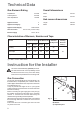
Procedure:
Re-ignite the burner and set to MIN.
Remove the control knob.
To adjust, use a thin bladed screwdriver and turn
the adjustment screw (see diagram) until the flame
is steady and does not extinguish, when the knob
is turned from MIN to MAX. Repeat this procedure
for all burners.
By-pass screw
Fig. 15