
Operating instructions


Manual Module M-G1 33300 08
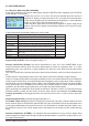
Channel select (OUTPUT CH): here you select the desired channel; the remainder of the settings in
this display only affect the channel which you select at this point.
Servo reverse (REVERSE): sests the direction of rotation of the connected servo
Normal: REVERSE OFF
Reverse: REVERSE ON
Servo centre (CENTER): The “CENTRE” line displays the current pulse width in μs of the control chan-
nel selected in the “OUTPUT CH” line. The displayed value varies according to the current position of
the transmitter control which affects this control channel, and also its trim position. A pulse width of 1500
μs corresponds to the standard centre position, and therefore the usual servo centre setting.
To change this value, select the “CENTRE” line and touch the INC + DEC buttons simultanously. Move
the corresponding transmitter control to the desired position, and touch the INC + DEC buttons again to
store the current transmitter control position. This position is now stored as the new neutral position.
Trim position (TRIM): The purpose of the “TRIM” line is to provide fi ne adjustment of the neutral po-
sition of a servo connected to the control channel selected in the “OUTPUT CH” line. Adjustments are
made in 1 μs increments using the INC or DEC buttons. The value in the “CENTRE” line can be adjusted
over the range +/- 120 μs around the TRIM value set here.
Servo travel (TRAVEL +/-): this function is used to adjust the maximum servo travel (control surface
travel) of the connected servo. The adjustment is available separately for each direction
Cycle time (PERIOD): at this point it is possible to defi ne the speed of the servos’ response to move-
ments of the transmitter controls. This adjustment applies to all channels.
Note: if you are using analogue servos, you must set a value of 20 msec. If you are using digital servos
exclusively, 10 msec should be selected.
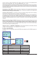
5.2.3 Failsafe Setup (RX FAIL SAFE)
To switch to the Failsafe setup display, press the ENTER button repeatedly until RX FAIL SAFE appears
on the screen.
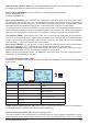
Display Description Setup
OUTPUT CH Output channel select 1 – X, depends on the connected
receiver
INPUT CH Input channel select 1 – 16
MODE Fail-safe Mode Fail Safe / Hold / Off
Factory setting Hold
F.S. Pos. Failsafe Position 1000 - 2000 usec
DELAY Failsafe response time 0.25, 0.50, 0.75, 1.00sec
Factory setting 0.75 sec.
FAIL SAFE ALL Stores fail-safe positions for all control
channels
NO / SAVE
POSITION Failsafe position 1000 - 2000 usec
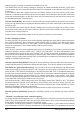
Output channel select (OUTPUT CH): this is where you select the desired channel; the remainder of
the fail-safe settings only affect the channel selected at this point.
Input channel select (INPUT CH): channel mapping function
The control functions can be distributed over several receivers in any sequence; alternatively multiple
receiver outputs can be assigned to the same control function. For example, this is useful if your aircraft
RX FAIL SAFE < >
OUTPUT CH: 01
INPUT CH : 01
MODE : FAI SAFE
F.S.Pos. : 1400usec
DELAY : 0.75sec
FAIL SAFE ALL : NO
POSITION : 1500usec
INC + DEC
INC
DEC
ENTER
ESC
INC + DEC
RX FAIL SAFE < >
OUTPUT CH: 01
INPUT CH : 01
MODE : FAI SAFE
F.S.Pos. : 1400usec
DELAY : 0.75sec
FAIL SAFE ALL : NO
POSITION : 1500usec