
Operating instructions


The limit values for receiver temperature which trigger a warning can be set in the RX SERVO TEST
display under ALARM TEMP+ (50 – 80°C) and ALARM TEMP- (-20 – +10°C).
If the receiver temperature rises above the maximum value or falls below the minimum, the unit genera-
tes an audible warning (continuous beeping). At the same time all the Smartbox receiver displays show
a fl ashing “TEMP.E” at top right, and the parameter R-TEM is shown in inverse form in the receiver data
display (RX DATAVIEW).
Data packets (L PACK TIME): indicates the duration of signal loss of the longest data packet during
transmission from transmitter to receiver, stated in msec. In practice this equates to the longest period
which the RC system has spent in fail-safe mode.
Operating voltage (R-VOLT): it is essential to monitor the operating voltage of the receiver constantly.
If it is too low, you must never launch your model or continue fl ying it.
The receiver low voltage warning can be adjusted in the RX SERVO TEST display under ALARM VOLT;
the available range is 3.0 to 6.0 Volt. If battery voltage falls to the threshold level, an audible signal
(continuous beeping) is emitted, and “VOLT.E” fl ashes at top right in all the Smartbox receiver displays.
At the same time the parameter R-VOLT is shown in inverse form in the receiver data display (RX DA-
TAVIEW).
Minimum operating voltage (L.R-VOLT): displays the lowest receiver operating voltage since the last
time the receiver was switched on. If this voltage differs signifi cantly from the actual operating voltage
R-VOLT, it is likely that the servos are placing an excessive load on the receiver battery, resulting in vol-
tage collapses. If this should occur, you should consider fi tting a larger or more robust receiver battery
in order to obtain maximum operating security.
Telemetry sensor 1 / 2 (SENSOR 1 / SENSOR 2): if these optional sensors are connected, their data
(Voltage / Volt and temperature / °C) is displayed live on the screen.
5.2.2
Servo data (RX SERVO)
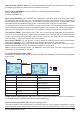
To switch to the servo data display, press the ENTER button repeatedly until RX SERVO appears on
the screen.
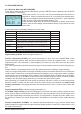
Display Description Setup
OUTPUT CH Channel select 1 – X, depends on the connected
receiver
REVERSE Servo reverse OFF / ON
CENTER Neutral point in usec. If active (highlighted), according
to transmitter control position
TRIM Trim position in usec. -120 – 120 usec
TRAVEL- Servo travel in %, negativ 30 – 150%
TRAVEL+ Servo travel in %, positiv 30 – 150%
PERIOD Cycle time in msec. 10 or 20 msec
07 Manual Module M-G1 33300
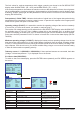
RX DATAVIEW >
S-QUA 100% S-dBm -49dBm
S-STR 065% R-TEM. +30°C
L PACK TIME 00005msec
R-VOLT : 05.9V
LR-VOLT : 05.8V
SENSOR1 : 00.0V 00°C
SENSOR2 : 00.0V 00°C
RX SERVO < >
OUTPUT CH: 01
REVERSE : ON
CENTER : 1500usec
TRIM : -000usec
TRAVEL- : 100%
TRAVEL+ : 100%
PERIOD : 20msec
INC + DEC
INC + DEC
INC
DEC
ENTER
ESC
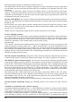
RX SERVO < >
OUTPUT CH: 01
REVERSE : ON
CENTER : 1500usec
TRIM : -000usec
TRAVEL- : 100%
TRAVEL+ : 100%
PERIOD : 20msec