
Operating instructions


Manual Module M-G1 33300 04
5. GENERAL NOTE
When switching on or adjusting the radio control system it is essential to keep the transmitter aerial at
least 15 cm away from the receiver aerials at all times. If the transmitter aerial is too close to the receiver
aerials, the receiver will be overloaded, causing the red LED on the receiver to light up. The transmitter
responds by emitting a beep once every second; the red LED also goes out. The radio control system
is now in Fail-Safe mode.
If this should occur, simply increase the distance between the aerials until the audible warning signal
ceases, and the red LED on the transmitter lights up again; at the same time the red LED on the receiver
should go out.
Please note: if you wish to switch the transmitter on again just after switching it off, please wait at least
fi ve seconds to ensure that the transmitter has time to shut down completely. If you neglect to do this,
there will be no connection between transmitter and receiver: you will hear a beep repeated about once
per second, and at the same time the red LED on the transmitter will go out, and the LED on the receiver
will fl ash red.
5.1. Transmitter Display (TX-Display)
The telemetry can be programmed directly on all HoTT transmitters whose telemetry menu is integrated
directly into the transmitter’s screen (this is possible with most models after a fi rmware update). If this
update is not carried out, programming is only possible using the SMART-BOX.
The SMART-BOX, Order No. 33700, must be used for programming if you are using any of the
following transmitters: mx-22, Order No. 4801 / 4802, mc-19, Order No. 4821, mc-22, Order No. 4818
and mc-18, Order No. 4835. The Smart Box is used instead of the interface cable connected to the
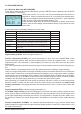
USB1 socket.The following instructions describe the method using the SMART-BOX; the table below
shows variations which apply to the Telemetry menu for the various models of transmitter:
SMART-BOX mx-12/16/20/32 HoTT mc-19/mc-22/mc-24/mx-24 HoTT
ENTER
ENTER
ESC
CLEAR
INC
scroll: value: scroll: push Rotary + value: Rotary
DEC
scroll: value: scroll: push Rotary + value: Rotary
INC+DEC SET push Rotary
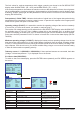
The TX screen appears when
- the SMART-BOX is connected to the DATA socket and the fi rst line „SETTING
AND DATAVIEW“ is activated by pressing the ENTER button
or
- transmitters with integrated telemetry: the menu item „telemetry“ is selected
press the Rotary
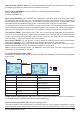
Display Description Setup
SD-card log Shows the saving process on the SD card ON /OFF automatic
A = TX VOLT Current operating voltage (V) -
M = MAXIMUM
VOLT
Maximum operating voltage (since the last power
on - V)
-
m = MINIMUM
VOLT
Minimum operating voltage (since the last power
on - V)
-
RX BIND Binding the receiver BINDING
ALARM VOLT voltage setup for transmitter low voltage warning
beep
4 – 15 V in steps of 0.5 V
Factory setting 9.3 V
COUNTRY Country setting GENERAL / FRANCE
RANGE TEST indicates if the range test is engaged, the remai-
ning
time also appears
OFF / ON
MULTIC 1 / 2
MULTIC 1 / 2
Multichannel 1 or 2 (Nautic-Expert-Module Order
Multichannel 1 or 2 (Nautic-Expert-Module Order
No. 4108)
No. 4108)
Channel select 1-X
(+ PERIOD: 20 msec,
CH OUTPUT TYPE:
SAME)
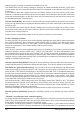
TX: SD-card log ON
A: 11.3 V M: 11.4V m: 11.2V
VARIO TONE: ON
RANGE TEST : OFF 90s
RX BIND : BIND
ALARM VOLT : 9.3V
COUNTRY :GENERAL
MULTIC1: 00 MULTIC2: 00