SERVICE MANUAL MICROWAVE OVENS Microwave Oven © ELECTROLUX HOME PRODUCTS Corso Lino Zanussi,30 I - 33080 PORCIA /PN (ITALY) Tel +39 0434 394850 Fax +39 0434 394096 Publication No. EMC3065X (947608328) 599 38 84-81 EN/SERVICE/FV SOI Edition: 05.2007 SOI 05.
PRECAUTIONS TO BE OBSERVED BEFORE AND DURING SERVICING TO AVOID POSSIBLE EXPOSURE TO EXCESSIVE MICROWAVE ENERGY (a) Do not operate or allow the oven to be operated with the door open.
1. SAFETY AND PRECAUTIONS 1. FOR SAFE OPERATION Damage that allows the microwave energy (that cooks or heats the food) to escape will result in poor cooking and may cause serious bodily injury to the operator. IF ANY OF THE FOLLOWING CONDITIONS EXIST, OPERATOR MUST NOT USE THE APPLIANCE. (Only a trained service personnel should make repairs.) (1) A broken door hinge. (2) A broken door viewing screen. (3) A broken front panel, oven cavity. (4) A loosened door lock. (5) A broken door lock.
2. SPECIFICATIONS KOC-9N4T7S, 9N4T7S24, MODEL POWER SUPPLY 230V~50Hz, SINGLE PHASE WITH EARTHING MICROWAVE POWER CONSUMPTION KOC-9N5T7R 9N5T7S, 9N5T7S21 1450W GRILL 850W CONVECTION 2250W 1450W COMBINATION 2950W 1450W MICROWAVE ENERGY OUTPUT 900W (IEC 705) MICROWAVE FREQUENCY 2450MHz OUTSIDE DIMENSIONS (W X H X D) 542X329X515mm(21.3X13.0X20.3 in.) CAVITY DIMENSIONS (W X H X D) 350X230X355mm(13.8X9.1X14.0 in.) NET WEIGHT Approx. 18Kg (39.6 lbs.
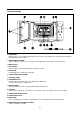
3. EXTERNAL VIEW 1.
2. FEATURE DIAGRAM 11. DOOR HOOK When the door is closed, it will automatically lock shut. If door is opened while oven is operating, the magnetron will immediately stop operating. 12. DOOR VIEWING SCREEN Allows viewing of food. The screen is designed so that light can pass through, but not the microwave. 13. METAL RACK 14. TOP HEATER Turns on when convection, grill and combi cooking is selected. 15. OVEN LAMP Automatically turns on during oven operating. 16. SAFETY INTERLOCK SYSTEM 17. CONTROL PANEL 18.
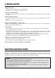
4. INSTALLATION 1. Steady, flat location This microwave oven should be set on a steady, flat surface. This microwave oven is designed for counter top use only. 2. Leave space behind and side All air vents should be kept a clearance. If all vents are covered during operation, the oven may overheat and, eventually, cause failure. 3. Away from Radio and TV sets Poor television reception and radio interference may result if the oven is located close to a TV, Radio, antenna or feeder and so on.
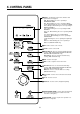
5. CONTROL PANEL 1 Display : Cooking time, power level, indicators and present time are displayed. MW : When blinking, the oven is operating in MICROWAVE COOK. Grill : When blinking, the oven is operating in GRILL. Combi : When blinking, the oven is operating in COMBI. Defrost Weight : When blinking, the oven is operating in WEIGHT DEFROST. Time : When blinking, the oven is operating in TIME DEFROST. Auto-cook : When blinking, the oven is operating AUTO COOK. Lock : When lighting, the oven is CHILD LOCK.
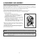
6. DISASSEMBLY AND ASSEMBLY - Cautions to be observed when trouble shooting. Unlike many other appliances, the microwave oven is high-voltage, high-current equipment. It is completely safe during normal operation. However, carelessness in servicing the oven can result in an electric shock or possible danger from a short circuit. You are asked to observe the following precautions carefully. 1. Always remove the power plug from the outlet before servicing. 2.
1. To remove cabinet 1) Remove four screws on cabinet back. 2) Push the cabinet backward. 2. To remove door assembly 1) Remove two screws which secure the stopper hinge top. 2) Remove the door assembly from top plate of cavity. 3) Reverse the above for assemby. NOTE: After replacing the door assembly, perform a check of correct alignment with the hinge and cavity front plate.
✔ Caution : In this Manual, some parts can be changed for improving, their performance without notice in the parts list. So, if you need the latest parts information, please refer to PPL(Parts Price List) in Service Information Center 3. To remove door parts. 1) KOC-9N4T/9N5T A10 A09 A08 A07 A11 A12 A04 A05 A06 A03 A13 A02 A01 REF NO.
4. Method to reduce the gap between the door seal and the oven front surface. (1) To reduce gap located on part ‘A’. • Loosen two screws on stopper hinge top, and then push the door to contact the door seal to oven front surface. • Tighten two screws. (2) To reduce gap located on part ‘B’. • Loosen two screws on stopper hinge under, and then push the door to contact the door seal to oven front surface. • Tighten two screws.
✔ Caution : In this Manual, some parts can be changed for improving, their performance without notice in the parts list. So, if you need the latest parts information, please refer to PPL(Parts Price List) in Service Information Center 2) KOC-9N5T7S,9N5T7R,9N5T7S21 REF NO.
6. To remove high voltage capacitor. 1) Remove a screw which secure the grounding ring terminal of the H.V. diode and the capacitor holder. 2) Remove the H.V. diode from the capacitor holder. 3) Reverse the above steps for reassembly. High voltage circuit wiring 7. To remove magnetron. 1) Remove a screw which secure the magnetron. 2) Remove the magnetron. 3) Reverse the above steps for reassembly.
8. To remove wind guide assembly. 1) Remove a screw for earthing. 2) Remove the noise filter from the wind guide. 3) Remove a screw which secure the wind guide assembly. 4) Draw forward the wind guide assembly. 5) Pull the fan from the motor shaft. 6) Remove two screws which secure the motor shaded pole. 7) Remove the motor shaded pole. 8) Reverse the above steps for reasembly. 9. To remove H.V.transformer. 1) Remove four screws holding the H.V.transformer. 2) Remove the H.V.transformer.
✔ Caution: In this Service Manual, some parts can be changed for improving, their performance without notice in the parts list. So, if you need the latest parts information, please refer to PPL(Parts Price List) in Service information Center 10. To remove Top heater assembly parts. 5 REF NO.
✔ Caution: In this Service Manual, some parts can be changed for improving, their performance without notice in the parts list. So, if you need the latest parts information, please refer to PPL(Parts Price List) in Service information Center 11. To remove Rear heater assembly parts. 14 13 12 11 10 15 9 8 16 17 7 6 1 5 4 3 2 REF NO.
7. INTERLOCK MECHANISM AND ADJUSTMENT The door lock mechanism is a device which has been specially designed to completely eliminate microwave radiation when the door is opened during operation, and thus to perfectly prevent the danger resulting from the leakage of microwave. (1) Primary interlock switch When the door is closed, the hook locks the oven door. If the door is not closed properly, the oven will not operate. When the door is closed, the hook pushes the button of the microswitch.
8. TROUBLE SHOOTING GUIDE Following the procedure below to check if the oven is defective or not. 1) Check grounding before trouble checking. 2) Be careful of the high voltage circuit. 3) Discharge the high voltage capacitor. 4) When checking the continuity of the switches, fuse or high voltage tranformer, disconnect one load wire from these parts and check continuity with the AC plug removed. To do otherwise may result in a false reading or damage to your meter.
CONDITION CHECK RESULT CAUSE REMEDY Outlet has proper voltage fuse does not blow? Check continuity of magnetron No continuity Defective magnetron. Replace Check continuity of noise filter board No continuity Defective line filter board Replace Check continuity of power supply cord No continuity Open power supply cord Replace No continuity Defective touch control circuit Replace NOTE : All these switches must be replaced at the same time, please refer to (7.
TROUBLE 3) No microwave oscillation even though fan motor rotates.
(TROUBLE 4) Grill heater (upper heater) is not heated; food will not become hot. CONDITION Grill heater is not heated. CHECK RESULT CAUSE REMEDY Check continuity of primary interlock switch No continuity Malfunction of primary Interlock switch Adjust or replace Check continuity of secondary interlock switch No continuity Malfunction of secondary interlock switch Adjust or replace Check continuity of heater No continuity Defective heater Check D.
(TROUBLE 6) The following visual conditions inditions indicate a probable defective touch control Circuit or button P.C.B. assembly 1. Incomplete segments. 1) segment missing 2) partial segments missing 3) digit flickering other than normal fluorescent slight flickering 2. A distinct change in the brightness of one or more numbers exists in the display. 3. One or more digits in the display are not on when they should be. 4. Display does not count down or up with time cooking or clock operation. 5.
9. MEASUREMENT AND TEST 1. MEASUREMENT OF THE MICROWAVE POWER OUTPUT Microwave output power can be checked by indirectly measuring the temperature rise of a certain amount of water exposed to the microwave as directed below. PROCEDURE 1. A cylindrical container of borosilicate glass is used for the test. It has a maximum thickness of 3mm, an external diameter of approximately 190mm and a height of approximately 90mm. The mass of the container is determined. 2.
2. MICROWAVE RADIATION TEST WARNING 1. Make sure to check the microwave leakage before and after repair of adjustment. 2. Always start measuring of an unknown field to assure safety for operating personnel from microwave energy. 3. Do not place your hands into any suspected microwave radiation field unless the safe density level is known. 4. Care should be taken not to place the eyes in direct line with the source of microwave energy. 5.
3. COMPONENT TEST PROCEDURE High voltage is present at the high voltage terminal of the high voltage transformer during any cooking cycle. It is neither necessary nor advisable to attempt measurement of the high voltage. Before touching any oven components or wiring, always unplug the oven from its power source and discharge the capacitor. 1. High voltage transformer 1) Remove connections from the transformer terminals and check continuity. 2) Normal readings should be as follows : Secondary winding ...
4.
10.