owner’s manual Audio/Video Receiver
IMPORTANT SAFETY INSTRUCTIONS This symbol is intended to alert you to the presence of dangerous voltage inside the product that can cause shock. Do not open the product’s case. This receiver is made and tested to meet exacting safety standards. It meets both UL and FCC requirements and complies with safety performance standards of the US Department of Health and Human Services.
IMPORTANT SAFETY INSTRUCTIONS Power Sources — Operate this product using only the power source indicated on its marking label. If you are not sure of your home’s power type, consult your product dealer or local power company. Polarization — This product is equipped with a polarized AC line plug (a plug having one blade wider than the other). This plug will fit in the power outlet only one way. This is a safety feature. If you cannot insert the plug fully into the outlet, try reversing the plug.
Table of Contents Introductory Information Supplied Accessories ............................. 7 To Improve AM Reception .............. 18 Placing the Receiver .............................. 7 Connecting Speakers ........................... 19 Avoiding Magnetic Interference ............. 7 Speaker Terminals ........................... 20 Installing the Batteries ........................... 7 A and B Speaker Systems ................ 20 Operating the Remote Control ..............
Table of Contents Setting Up the Receiver Choosing Your Receiver Setup ............. 34 Speaker Setting ............................... 35 Subwoofer Setting ........................... 35 Crossover Frequency Setting ........... 35 LFE Attenuator Setting .................... 36 Front Speaker Distance Setting ........ 36 Center Speaker Distance Setting ...... 36 Surround Speaker Distance Setting ..............................
Introductory Information Congratulations on buying this fine RCA product. Please read through these operating instructions so you will know how to operate your model properly. After you have finished reading the instructions, put them away in a safe place for future reference. Your RCA Audio/Video Receiver has the following benefits. R — DTS is a digital sound system introduced in theaters.
Introductory Information Supplied Accessories Please check that you have received the following supplied accessories: • AM loop antenna • FM wire antenna • Remote control • Owner’s manual Placing the Receiver Please note the following points: • Do not place objects directly on top of this unit. This prevents proper heat dispersal. • When installing on a rack, shelf, etc., be sure to leave more than 8 inches (20 cm.) of space above the receiver.
5 Minute Guide Introduction to Home Theater You are probably used to using stereo equipment to listen to music, but may not be used to home theater systems that give you many more options (such as surround sound) when listening to soundtracks. Home theater refers to the use of multiple audio channels to create a surround sound effect, making you feel like you are in the middle of the action or concert.
5 Minute Guide Listening to Surround Sound This receiver was designed with the easiest possible setup in mind, so with the following quick setup guide, you should have your system connected for surround sound in no time at all. In most cases, you can simply use the receiver’s default settings. 1 Connect your DVD player. For surround sound, you need to make a digital connection from the DVD player to the receiver. You can do this with either a coaxial, or an optical connection (you do not need to do both).
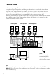
5 Minute Guide 3 Connect your speakers. A complete setup of six speakers, including the subwoofer, is shown below. Actual home setups may vary. Simply connect the speakers you have as shown. The receiver will work with just a pair of stereo speakers (the front speakers in the diagram), but using at least three speakers (two front and a center) is recommended, and a complete setup is best. Make sure you connect the speaker on the right to the right terminal and the speaker on the left to the left terminal.
5 Minute Guide 4 Plug in the receiver and switch it on, followed by your DVD player, your subwoofer and the TV. Make sure to set the video input on your TV to this receiver. Check the manual that came with the TV if you do not know how to do this. Also make sure that DVD is showing in the receiver’s display, indicating that the DVD input is selected. If it is not, press DVD to set the receiver to the DVD input. 5 Press SETUP on the front panel to specify your speaker setup and your room size.
5 Minute Guide Using the Quick Setup You can use the Quick Setup to get your system up and running with just a few button presses. The receiver automatically makes the necessary settings after you have selected your speaker setup and room size. If you want to make more specific settings, refer to “Choosing Your Receiver Setup” on pages 34–39. Use the front panel controls for the steps below. Note: Check the table below to find the speaker setup that corresponds with your system.
Connecting Your Equipment Before making or changing the connections, switch off the power and disconnect the power cord from the AC outlet. Audio/Video Cables Component Video Cables Use audio/video cables (not supplied) to connect the audio/video components and a video cable to connect the monitor TV. Use component video cables to get the best possible color reproduction of your video source. The video signal is divided into the luminance (Y) signal and the color (PB and PR) signals and then output.
Connecting Your Equipment Connecting Digital Components The easiest way to connect this receiver for surround sound is to use a digital input. You can do this by either coaxial or optical connections (you do not need to do both). The quality of these two types of connections is the same but since some digital components have only one type of digital terminal, it is a matter of matching like terminals (for example, the coaxial output from the component to coaxial input on the receiver).
Connecting Your Equipment Connecting Audio Components For components you want to use to record, you must connect four plugs to the receiver (a set of stereo ins and a set of stereo outs). For components that only play, you only need to connect one set of stereo plugs. You must also connect your digital components to analog audio jacks if you want to record to/from digital components (like an MD) to/from analog components. See page 14 for more on digital connections.
Connecting Your Equipment Connecting DVD 5.1 Channel Components If you have a DVD player with multi-channel analog outputs, or prefer to use an external decoder, you can connect it to this receiver’s multi-channel analog inputs. When connecting your equipment, always make sure the power is turned off and the power cord is disconnected from the AC outlet. The arrows indicate the direction of the audio signal. DVD/multi-channel decoder with 5.
Connecting Your Equipment Connecting Video Components Connect your video components to the jacks as shown below. With digital video components (like a DVD player), you must use the connections shown on this page for the video signal, but in order to hear a digital source (like a DVD) you should connect the audio to a digital input (see page 14). It is also a good idea to connect your digital components with analog audio connections (see page 15).
Connecting Your Equipment Connecting Antennas Antenna Snap Connectors Connect the AM loop antenna and the FM wire antenna. To improve reception and sound quality, connect external antennas (see “Using External Antennas”). Always make sure that the receiver is switched off and unplugged from the wall outlet before making or changing any connections. Twist the exposed wire strands together and insert into the hole, then snap the connector shut. 3/8 in.
Connecting Your Equipment Connecting Speakers A complete setup of six speakers (including the subwoofer) is shown below, but actual home setups may vary. Connect the speakers as shown below. The receiver will work with just a pair of stereo speakers (the front speakers in the diagram), but using at least three speakers (two front and a center) is recommended, and a complete setup is best. Make sure you connect the speaker on the right to the right terminal and the speaker on the left to the left terminal.
Connecting Your Equipment Speaker Terminals 1 Twist exposed wire strands together. 3/8 in. (10mm) 2 Loosen speaker terminal and insert exposed wire. 3 Tighten terminal. The speaker terminals also accept single banana plugs. (Refer to speaker manual for details.) Caution: Make sure that all the bare speaker wire is twisted together and inserted fully into the speaker terminal. If any of the bare speaker wire touches the back panel it may cause the power to cut off as a safety measure.
Connecting Your Equipment Hints on Speaker Placement Speakers are usually designed with a particular placement in mind. Some are designed to be floorstanding, while others should be placed on stands to sound their best. Some should be placed near a wall; others should be placed away from walls. Follow the guidelines on placement that the speaker manufacturer provided with your particular speakers to get the most out of them. • Place the front left and right speakers at equal distances from the TV.
Connecting Your Equipment AC Outlet Power supplied through this outlet is turned on and off by the receiver's POWER switch. Total electrical power consumption of connected equipment should not exceed 100 W (0.8 A). Caution: Do not connect a heater, TV or any other kind of heavy appliance. Also, make sure no exposed speaker wire is touching the rear panel, as this may cause the receiver to turn off automatically.
Controls and Displays Front Panel 1 2 3 4 5 R MULTI JOG MULTI JOG ENTER STANDBY POWER VOLUME PRESET TUNING TUNING STANDARD ADVANCED SURROUND STEREO/ DIRECT SIGNAL SELECT MIDNIGHT SPEAKERS MONITOR TONE SETUP UP DOWN OFF MULTI JOG LISTENING MODE ON TUNER EDIT CLASS BAND MPX INPUT ATT FL DIMMER MULTI JOG S-VIDEO PHONES VIDEO L VIDEO INPUT AUDIO R 7 6 8 9 PRESET TUNING TUNING 10 STANDARD ADVANCED SURROUND 11 12 13 14 15 16 STEREO/ DIRECT SIGNAL SELECT MIDNIGHT SPEAKER
Controls and Displays 11 SIGNAL SELECT button (pages 30, 32–33) 18 FL DIMMER button Use this button to make the fluorescent display (FL) dimmer or brighter. Use to select an analog or digital signal. 12 MIDNIGHT button (page 32) 19 INPUT ATT button Use Midnight when listening to movie soundtracks at low volume. Use to attenuate (lower) the level of an analog input signal to prevent distortion.
Controls and Displays 2 DTS When the Standard mode of the receiver is on, this lights to indicate decoding of a DTS signal. 3 2 DIGITAL When the Standard mode of the receiver is on, this lights to indicate decoding of a Dolby Digital signal. 4 2 PRO LOGIC II When the Standard mode of the receiver is on, this lights to indicate Pro Logic II decoding. 5 ATT Lights when INPUT ATT is used to attenuate (reduce) the level of the analog input signal. 6 DIRECT Lights when source direct playback is in use.
Controls and Displays Remote Control 10 1 2 3 11 1 SOURCE POWER Press to turn on/off other components connected to the receiver. 2 MULTI CONTROL buttons Press to select control of other components (see “Controlling the Rest of Your System” on pages 44–61). 4 3 RCV Switches the remote to control the receiver (used to select the features above the number buttons. (ex. INPUT ATT, FL DIMMER)). Also use this button to set up surround sound (pages 34, 39).
Controls and Displays CH SELECT (page 39) CLASS (pages 41–42) Selects a speaker when setting up the surround sound of the receiver. Switches between the three banks (classes) of radio station presets. − (page 39) LEVEL +/− DTV/DISP Adjusts the levels of the surround sound of the receiver. Switches a digital TV on/off. It can also be used to switch the display between the station preset name and the frequency for the tuner.
Controls and Displays SIGNAL SEL (pages 30, 32–33) 14 MASTER VOLUME +/– Use to select between an analog or digital signal. 15 MENU button INPUT SEL Use to select the input source. NIGHT LOUD (page 32) Switches to Midnight or Loudness listening. MUTE Mutes the sound (or restores the sound if it has been muted). 9 TV control buttons These buttons are for controlling the TV assigned to the TVC button. If you have two TVs, assign the main TV to the TVC button.
Playing Sources Introduction to Sound Modes Choose one of the following to add depth to a 2 channel source: There are three basic sound options: Stereo/ Direct, Standard and Advanced Surround. Pro Logic Stereo/Direct When you select STEREO or DIRECT, you will hear the source through just the front left and right speakers (and possibly your subwoofer depending on your speaker settings). Dolby Digital and DTS multichannel sources are downmixed to stereo.
Playing Sources Music Simulates the acoustic environment of a large concert hall and is suitable for music or ) musical sources marked 1 ( RECEIVER POWER SOURCE POWER DVD TV VCR CD-R MULTI CONTROL RCV TUN CD TVC R or . 1 2 TEST TONE INPUT ATT 4 5 3 FL DIMMER 6 CH SELECT LEVEL 8 7 Virtual Rear Center Channel (VIRTL SB) EFFECT 0 DTV INFO The Virtual Rear Center Channel effect simulates 6.
Playing Sources • Some DVD players do not output DTS signals. For more details, refer to the instruction manual supplied with your DVD player. Listening to MultiChannel Playback Pro Logic Pro Logic II Music Pro Logic II Movie 4 Start playback of the component you selected in step 1.
Playing Sources Each press changes the display as follows: Movie Music VIRTL SB 5-Stereo Expanded Using the Tone Controls Depending on what you are listening to, you may want to adjust the bass or treble using the front panel tone control. R Refer to page 29 for more details about each surround effect. MULTI JOG MULTI JOG ENTER VOLUME Note: The Movie, Music, and Expanded effect level can be adjusted in the range of 10 to 90 (the default setting is 70) by pressing EFFECT +/—.
Playing Sources Playing Other Sources RECEIVER POWER SOURCE POWER DVD TV VCR CD-R MULTI CONTROL RECEIVER POWER SOURCE POWER DVD TV VCR CD-R RCV 1 2 TEST TONE INPUT ATT 4 5 MULTI CONTROL RCV TUN CD TVC 2 3 FL DIMMER 4 5 6 9 EFFECT 0 DTV INFO MPX/RETURN DISC 7 3 8 CLASS DTV/DISP DTV MENU 1 ¡ 4 ¢ AUDIO SUB TITLE ¶ 7 CLASS DISC ENTER D ACCESS T EDIT/GUIDE 3 8 DTV/DISP DTV MENU ¡ 4 AUDIO SUB TITLE ANGLE STANDARD ADV SURR STEREO SIGNAL SEL NIGHT LOUD
Setting Up the Receiver Choosing Your Receiver Setup • Speaker setting (page 35) To ensure the best possible surround sound, be sure to complete the following setup procedure. This is particularly important when using Dolby surround. You only need to make these settings once (unless you change the placement of your current speaker system or add new speakers). Refer to the following pages for details on each of the settings.
Setting Up the Receiver 4 Use ’ or ‘ to adjust the setting. The setting is entered automatically. 5 Repeat steps 3 and 4 to set other surround modes. 6 When you are done, press ENTER to exit. Note: The receiver automatically exits setup mode after 20 seconds of inactivity.
Setting Up the Receiver to the subwoofer (or if you do not have a subwoofer, the large (L) speakers in your system) instead of the speakers set to small (S) in your setup. Choose the point at which you want the frequency routed to the subwoofer (or L speakers). We recommend setting this to 200 Hz if your S speakers are smaller bookshelf-type speakers. Use ’ or ‘ to specify the crossover frequency for your small speakers (100 Hz, 150 Hz or 200 Hz).
Setting Up the Receiver Use ’ or ‘ to set the distance of the center speaker from the main listening position (within a 30 foot range). Note: When C is selected in the speaker setting, the center speaker distance cannot be set. * Surround Speaker Distance Setting Default setting: 10 ft. Like the center speaker, you should set the distance of the surround speakers accurately to hear sounds coming from both front and surround speakers at the same time.
Setting Up the Receiver Component Video Input Settings Here you tell the receiver what components you have connected to the component video jacks on the back of the receiver. Component video 1: Default setting: DVD Use ’ or ‘ to assign the component video 1 input (DVD, TV, VCR or OFF). Component video 2: Default setting: TV Use ’ or ‘ to assign the component video 2 input (DVD, TV, VCR or OFF).
Setting Up the Receiver Setting the Relative Volume Level of Each Channel Default setting: 0 dB. For best surround sound playback, you should set the relative channel levels from the main listening position. You can set separate levels for each surround mode.
Using the Tuner Listening to the Radio The following steps show you how to tune in to FM and AM radio broadcasts using the automatic (search) and manual (step) tuning functions. If you already know the frequency of the station you want, see “Tuning Directly to a Station” below. Once you are tuned to a station you can memorize the frequency for recall later—see “Saving Station Presets” on the next page for more on how to do this.
Using the Tuner 4 Use the number buttons to enter the frequency of the radio station. For example, to tune to 106.1 (FM), press 1, 0, 6, 1. STEREO FM PRESET TUNING STANDARD TUNING ADVANCED SURROUND STEREO/ DIRECT SIGNAL SELECT MIDNIGHT SPEAKERS MONITOR CLASS BAND MPX INPUT ATT TONE SETUP MULTI JOG LISTENING MODE TUNER EDIT FL DIMMER MULTI JOG S-VIDEO VIDEO L VIDEO INPUT AUDIO R TUNED SP A 106.
Using the Tuner 4 Press ENTER. The preset class and number stop blinking and the receiver stores the station you want to listen. Listening to Station Presets 1 Press TUN (remote) or use the MULTI JOG dial on the front panel to select the tuner. 2 Press CLASS to select the class in which the station is stored. Press repeatedly to cycle through classes A, B and C. 3 Press P-SET }/](PRESET TUNING @/#) to select the station preset you want.
Making a Recording Making an Audio or a Video Recording You can make an audio or a video recording from the built-in tuner, or from an audio or video source connected to the receiver (such as a CD player or TV). Keep in mind you cannot make a digital recording from an analog source or vice-versa, so make sure the components you are recording to/from are connected in the same way (see pages 14, 15, 17 for more on connections).
Controlling the Rest of Your System Setting the Remote to Control Other Components There are several ways to set your remote to control the other components in your system. The easiest way to do this is to assign the component’s manufacturer preset code (listed on pages 51–61) to one of the MULTI CONTROL buttons on the remote control. You can do this directly, or by searching through different preset codes until you find the right one.
Controlling the Rest of Your System Notes: • If you assign a preset code for the TUN button, you will not be able to control the built-in tuner using the remote. Reset the remote to the built-in tuner by entering the preset code 7008. • To erase the preset code for the current MULTI CONTROL button, enter 0000 as the preset code. 4 Repeat steps 1 through 3 for the other components you want to control. Searching for Preset Codes Another way of entering preset codes is to use the search feature.
Controlling the Rest of Your System Erasing a Remote Control Button Setting This erases one of the buttons you have programmed and restores the button to the factory default. 1 Press and hold REMOTE SETUP for three seconds. The LED lights steadily for two seconds. 2 Press the MULTI CONTROL button for the setting to be erased. 3 Press the RECEIVER POWER button twice quickly. The LED blinks to indicate the remote is ready to erase the button setting.
Controlling the Rest of Your System Note: You cannot use direct function for TV INPUT. Confirming Preset Codes Use this feature to check which preset code is assigned to a MULTI CONTROL button. 1 Press and hold REMOTE SETUP for three seconds. The LED lights steadily for two seconds. 2 Press the MULTI CONTROL button of the component for which you want to check the preset code. 3 Press and hold ENTER for two seconds. Each preset code consists of four digits, for example 1329.
Controlling the Rest of Your System Controls for TVs This remote control can control components after entering the proper codes (see pages 44– 46). Use the MULTI CONTROL buttons to select the component. Function Button (s) TV DTV Press to switch the TV or CATV between standby and on. Cable TV/Satellite TV/TV TV INPUT Press to switch the TV input. (Not possible with all models. If it does not work with the preset code, use the learning feature.) TV CHANNEL Select channels.
Controlling the Rest of Your System Button (s) Function Components }]’‘ & Select or adjust and navigate items on the menu screen. ENTER ENTER brings up the DTV menus. EFFECT +/– DTV Press to select or adjust and navigate items on the menu screen. Cable TV/Satellite TV/TV/ DTV For TV and cable TV use this button to immediately enter a new channel (CHANNEL ENTER function). For satellite TV use this button to exit the menu screen.
Controlling the Rest of Your System Button (s) Function Start playback. 7 Stop playback (on some models, pressing this when the CD/MD/CD-R/VCR/DVD/LD/ disc is already stopped will cause the disc tray to open). DVR player/Cassette deck ¶ Start recording. To prevent accidental recording, this button must be pressed twice to take effect (the second press must be within 10 seconds of the first). VCR/DVR player Number buttons Directly access tracks on a program source.
Controlling the Rest of Your System Preset Code List You should have no problem controlling a component if you find the manufacturer in this list, but you can only set these codes for the button that is assigned to that component. So, for example, the TV codes can only be set to the TV or TVC button.
Controlling the Rest of Your System 52 CLARIVOX 1017 CLATRONIC 1036, 1086, 1102 CME 1007, 1015, 1114 CONCERTO 1026 CONDOR 1098, 1102 CONTEC 1006, 1016, 1064, 1078 CONTINENTAL EDISON 1069, 1070, 1072 CRAIG 1054 CROSLEY 1025, 1034, 1036, 1038, 1075 CROWN 1006, 1017, 1019, 1036, 1064, 1102, 1106 CRYSTAL 1109 CS ELECTRONICS 1078 CTC 1086 CURTIS MATHES 1009, 1013, 1019, 1022, 1023, 1025, 1026, 1027, 1041, 1047, 1050, 1057, 1110, 1113, 1129, 1131 CYBERTRON 1080 CXC 1064 DAINICHI 1077, 1080 DANSAI 1017 DAYTRON 1
Controlling the Rest of Your System KTV LEYCO LG LIESENK&TTER LLOYTRON LOEWE LOGIK LUMA LUXMAN LXI M ELECTRONIC MAGNAVOX MAGNADYNE MAGNAFON MAJESTIC MANESTH MARANTZ MARK MATSUI MATSUSHITA MCMICHAEL MEDIATOR MEGATRON MEMOREX METZ MGA MIDLAND MINERVA MINOKA MINUTZ MIVAR MOTION MOTOROLA MTC MULTITECH NAD NEC NECKERMANN NEI NETSAT NICAMAGIC NIKKAI NIKKO NOBLIKO NORDMENDE NTC OCEANIC ONWA OPTIMUS OPTONICA OSAKI 1013, 1019, 1064 1017, 1032, 1089, 1095 1026 1017 1014 1035, 1114 1009 1073 1026 1022, 1025, 1050, 10
Controlling the Rest of Your System SANYO SBR SCHNEIDER SCIMITSU SCOTCH SCOTT SEARS SEG SEI SEI-SINUDYNE SELECO SEMIVOX SEMP SENTRA SHOGUN SHORAI SSS SIAREM SINDYNE SIGNATURE SILVER SKY SKY-WORTH SOLAVOX SONITRON SONOKO SONOLOR SONTEC SOUNDESIGN SOUNDWAVE SQUAREVIEW STANDARD STARLITE STERN SUNKAI SUPERTECH SUPREME SUSUMU SYLVANIA SYMPHONIC SYSLINE TANDY TASHIKO TEC TECHNEMA TECHNICS TECHNOL ACE TECHWOOD TEKNIKA 54 TELEAVIA TELEMEISTER TELETECH TELETON TENSAI 1016, 1032, 1048, 1050, 1052, 1074, 1075, 1100
Controlling the Rest of Your System FUNAI HITACHI HONG DENG IDALL KEBAO MARANTZ MITSUBISHI NAD PANASONIC PHILIPS RADIOLA ROWA SALORA SEGA SHARP SHINCO SMC SONY SUPER TELEFUNKEN TOSHIBA PIONEER CD PLAYER Manufacturer 5217 5201 5213 5219 5215 5203, 5205 5202 5202 5210 5203, 5207, 5209 5207 5212 5203 5201 5221 5211 5220 5204, 5206, 5216 5218 5215 5202 5223 5201,5202, 5208 5214 CD CD-R Code AIWA 5016, 5021 AKAI 5014, 5020, 5032 ANAM 5041 ARCAM 5021 AUDIOLAB 5021 AUDIOMECA 5021 AUDIO TON 5021 BESTAR 5022 BU
Controlling the Rest of Your System WARDS PIONEER TAPE DECK 56 5010, 5021 5005, 5030, 5035, 5038, 5048, 5052, 5063 CD-R CD Manufacturer Code ADC AIWA AKAI ANAM ARCAM CARVER DENON DUAL DYNAMIC BASS EROICA FISHER GARRARD GOLDSTAR GRUNDIG HARMON/KARDON INKEL JVC KENWOOD KYOCERA LOTTE LUXMAN MAGNAVOX MARANTZ MEMOREX MITSUBISHI NAKAMICHI NIKKO OLYMPUS ONKYO OPTIMUS PANASONIC PHILIPS RCA RENAISSANCE REVOX SAMSUNG SANSUI SANYO SHARP SONIC SONY TEAC TECHNICS THORENS VICTOR WARDS YAMAHA PIONEER 6013 6002, 60
Controlling the Rest of Your System CAPETRONIC CARVER CURTIS DAEWOO DENON DUAL EROICA FANTASIA FERGUSON FINE ARTS FISHER GARRARD GOLDSTAR GOODMANS GP AUDIO GRUNDIG HARMAN/KARDON INKEL JBL JVC KENWOOD LOTTE LUXMAN MAGNAVOX MARANTZ MCINTOSH MCS MCSILVER MICROMEGE NIKKO OPTIMUS ONKYO PALLADIUM PANASONIC PHILIPS PHONOTREND QUASAR RCA RENAISSANCE REVOX ROADSTAR SABA SAISHO SAMSUNG SANSUI SANYO SCHNEIDER SHARP SHERWOOD SOUNDESIGN SONY TAE KWANG TEAC TECHNICS TELEFUNKEN 7042 7055, 7059 7008 7032 7001, 7056, 7058
Controlling the Rest of Your System 58 BELL & HOWELL 2037 BRANDT 2047, 2064, 2065 BRANDT ELECTRONIC 2021 BROKSONIC 2002, 2040, 2046, 2052, 2078 BUSH 2034, 2052, 2059, 2072 CALIX 2017 CANON 2015 CAPEHART 2011 CARVER 2035 CATRON 2011 CCE 2034, 2059 CGE 2001 CIMLINE 2034 CINERAL 2059 CITIZEN 2017, 2059 CLATRONIC 2011 COLT 2034 COMBITECH 2072 CONDOR 2011 CRAIG 2017, 2026, 2034, 2057, 2058 CROWN 2011, 2034, 2059 CURTIS MATHES 2015, 2021, 2032, 2042 CYBERNEX 2057 CYRUS 2035 DAEWOO 2011, 2024, 2025, 2059, 2083 D
Controlling the Rest of Your System MINERVA MINOLTA MOTOROLA MTC MULTITECH MURPHY NAD NATIONAL NEC NECKERMANN NESCO NIKKO NIKON NOBLEX NOKIA NORDMENDE OCEANIC OKANO OLYMPUS OPTIMUS OSAKI OTTO VERSAND PALLADIUM PATHE MARCONI PATHE CINEMA PENTAX PENNY PERDIO PHILCO PHONOLA PILOT PORTLAND PROFEX PROFITRONIC PROLINE PROSCAN PROTEC PULSAR PYE QUARTER QUARTZ QUASAR QUELLE RADIO SHACK RADIOLA RADIX RANDEX RCA REALISTIC REX RFT RICOH ROADSTAR RUNCO 2005, 2010, 2048 2022 2015, 2027 2001, 2057 2001, 2034 2001 2031 2
Controlling the Rest of Your System VICTOR VIDEO CONCEPTS VIDEOSONIC WARDS 2008, 2021, 2033 2020, 2024 2057 2001, 2015, 2022, 2026, 2027, 2032, 2034, 2035, 2057 WHITE WESTINGHOUSE 2052, 2059 XR-1000 2001 XR-1001 2015 XR-1002 2034 YAMAHA 2018 YAMISHI 2034 YOKAN 2034 YOKO 2011, 2057 ZENITH 2001, 2014, 2019, 2052, 2078 PIONEER 2031, 2033, 2035, 2044, 2056 SATELLITE TUNER Manufacturer ABSAT AST ALBA ALDES AMSTRAD 60 TV TVC Code 4006 4027 4029, 4034, 4037, 4052 4019 4003, 4016, 4025, 4038, 4039, 4042 ANKA
Controlling the Rest of Your System PLANET PROMAX PROSAT QUADRAL RADIOLA RADIX RCA RFT SAT SABA SABRE SAGEM SALORA SATCOM SATEC SATMASTER SATPARTNER SCHWAIGER SEEMANN SEG SIEMENS SKYMASTER SONY STRONG SUNSTAR TPS TANTEC TECHNISAT TECHNILAND TELEFUNKEN TELEKA TELESAT TONNA TRIAD TRIASAT UNITOR UNIVERSUM VENTANA VORTEC VTECH WINERSAT WISI XSAT XCOM MULTIMEDIA ZEHNDER CABLE TV Manufacturer 4061 4037 4019 4029, 4044 4011 4031, 4064 4037, 4059 4011, 4013, 4019 4027, 4038 4023, 4045 4037 4056 4005 4026, 4051 40
Additional Information Troubleshooting Incorrect operations are often mistaken for trouble and malfunctions. If you think that there is something wrong with this component, check the points below. Sometimes the trouble may lie in another component. Investigate the other components and electrical appliances being used. If the trouble cannot be resolved by following the the suggested remedies below, take the unit to your nearest local RadioShack store.
Additional Information Problem Remedy No sound from surround or center speakers. • Refer to “Speaker Setting” on page 35 to check the speaker settings. • Refer to “Setting the Relative Volume Level of Each Channel” on page 39 to check the speaker levels. • Connect the speakers properly (refer to pages 19–21). Noise during playback of a cassette Move the cassette deck further from your receiver, until the noise deck. disappears. Sound is produced from other components, but not from LD or DVD player.
Additional Information Specifications Amplifier Section Continuous average power output of 100 watts* per channel, min., at 8 ohms, from 20 Hz to 20,000 Hz with no more than 0.2 %** total harmonic distortion (front). Continuous Power Output Front .............................. 100 W per channel (1kHz, 1.0 %, 8 Ω) Center ................ 100 W (1kHz, 1.0 %, 8 Ω) Surround ....................... 100 W per channel (1kHz, 1.
Additional Information Miscellaneous Power Requirements ......... AC 120 V, 60 Hz Power Consumption ......................... 260 W In Standby ............................................ 1 W AC Outlet ........ 100 W MAX. (SWITCHED) Dimensions (WHD) 16-9/16 x 6-4/16 x 15-6/16 in. 420 x 158 x 401 mm Weight (without package) ................................. 19 lb 3 oz (8.7 kg ) Furnished Parts AM loop antenna ...................................... FM wire antenna .......................................
Additional Information 66
Additional Information 67
Limited Two-Year Warranty This product is warranted by RadioShack against manufacturing defects in material and workmanship under normal use for two (2) years from the date of purchase from RadioShack companyowned stores and authorized RadioShack franchisees and dealers.