
Service manual


8
97-05
Replacing the mother board
Should the replacement of the mother board be necessary
it is important that the parameter memory corresponds to
the type of microprocessor which comes in several different
versions.
- If the microprocessor version of the old mother board is
the same as the new one:
- Take the memory chip off the old board and fit it on the
new board.
- If you wish to use the new board without recovering either
the memory chip from the old board you will have to
reprogram all the user conditions by following the chapter
"Parameter programming". Remember that the history of
the oven will have been lost along with any of the customer's
personalised parameters.
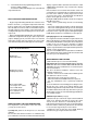
Dismantling integrated circuits (memory, microproces-
sors etc.)
To remove integrated circuits from their seat, insert a
screwdriver into the space between the chip and its base
(fig3) and lever slightly (first from one end and then from the
other) in order to free the chip from its base without
damaging the pins.
The direction of the microprocessor or the memory chip
must be respected when inserting it into its base. To this
end both the integrated circuit and the base are marked with
a tab or a point which indicates the correct alignment.
Incorrect alignment could damage both the integrated
circuit and the P.c.b. card.
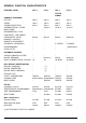
Function level and microprocessor compatibility table
Each card has a list of parameters specific to the type of
microprocessor. This means that the number marked on
the microprocessor must correspond to the number in the
parameter list. It is important therefore that you conserve all
parameter lists which are sent to you. It is however possible
to mount a card which has the latest up to date memory
chips in place of a previous generation card in this case the
parameters will have to be reprogrammed. The parameter
lists always carry the drawing code 599879400 or 599879400
on which the microprocessor version is also indicated. The
following is a list of the various microprocessors and their
compatibility.
LEVELS/Microproc. 4.02 4.04 4.05 4.11 6.03
Versions
Level 2 ISG OK OK OK OK OK
Level 3 ISG no no no OK OK
Level 3 BOILER OK OK OK OK OK
Level 4 BOILER OK OK OK OK OK
Level 6 BOILER no no OK/P OK/P OK
Example: If you attempt to fit a card, on which a 4.04
microprocessor is mounted, to a level 3 ISG oven the
correct operation of the appliance cannot be guaranteed.
USER INTERFACE CARD UIA
If a user interface card UIA is to be replaced the potentiometer
will have to be recalibrated by entering the parameter
programming function.
DISPLAYING THE PROBE TEMPERATURE, LAMP
TEST AND WATER BOILING POINT SETTINGS
In spite of the function level it is possible to display several
parameters while the oven is being used by pressing the
service buttons on the control panel as follows.
Service buttons
• Three buttons, which for simplicity we will call A,B and
C (see fig.4), are present towards the bottom of the control
panel on all versions and models and can be operated
externally. In some cases the buttons are visible because
they indicate functions which are to be used by the operator,
in other cases however they are not visible but can be
recognised by the slight bulging in the control panel
membrane. In models where there are more than three
buttons in this position the central button is always to be
considered “B” while the buttons immediately to the left and
right of the central button are always the “A” and “C” buttons
respectively.
• The various functions of the service buttons are indi-
cated on the oven chamber temperature display (fig. 4) as
described below.
• The service buttons are divided into 2 major groups:
1. - Displaying the temperature of the boiler and by pass
(vapour damping temperature).
- Lamp test
- Water boiling point calibration
Cavity Display
Fig. 4
A,B,C = Service buttons
A
B
B
C